Download
1 / 15
150 likes | 250 Views
Programmable Controller Basics Analog Control. MicroLogix Packaged Controllers. What is an Analog Signal? g I/O. Analog Signal: The representation of numerical quantities by the measurement of continuous physical variables. Answer.

E N D
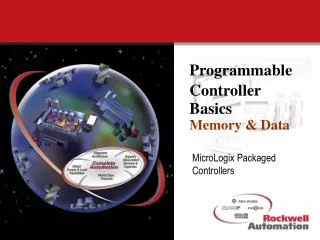
Programmable Controller BasicsAnalog Control MicroLogix Packaged Controllers
What is an Analog Signal?g I/O Analog Signal: The representation of numerical quantities by the measurement of continuous physical variables.
Answer Unlike Discrete signals, which have only 2 states (ON and OFF). Analog signals can have an infinite number of states. Temperature is an example of an analog signal. This signal is constantly changing by infinitesimal amounts. A change from 700F to 710 F degrees is not just a 10F change but a infinite number of smaller fractions of that 10F.
S Analog input interface 0000000000000000 PLC Word/Bit file of Memory T Continuous Signal Analog to Digital Converter Analog Input Signals Analog Input Interface:Translates the continuous analog input signals into discrete values with in the PLC. (analog to digital converter)
Analog Input Devices • Flow Transducers • Humidity Transducers • Load Cell Transducers • Potentiometers • Pressure Transducers • Vibration Transducers • Temperature Transducers
Analog input Signal ratings • Voltage Range • 10V dc • 0 to 10V dc • 0 to 5V dc • 1 to 5V dc • Current Range • 20 mA • 0 to 20 mA • 4 to 20 mA • Unipolar: Positive voltage only • Bipolar: Positive and Negative
S Analog Output Interface 0000000000000000 PLC Word/Bit file of Memory T Continuous Signal (voltage or current) Digital to analog converter Analog Output signals Analog Output Interface:Translates the discrete values of the PLC into continuous analog output signals. (digital to analog converter)
Analog Output Field Devices • Analog Valves • Actuators • Chart Recorders • Motor Drives • Analog Meters • Pressure Transducers
Analog output Signal ratings • Current Range • 0 to 21 mA • 0 to 20 mA • 4 to 20 mA • Voltage Range • 10V dc • 0 to 10V dc • 0 to 5V dc • 1 to 5V dc • Unipolar: Positive voltage only • Bipolar: Positive and Negative
Resolution Resolution:The smallest detectable increment of measurement This is a reference to the accuracy of the A/D converter. 15bit = Signal/32767 (0 to 32766 steps) 14bit = Signal/16384 (0 to 16383 steps) 13bit = Signal/ 8192 (0 to 8193 steps) 12bit = Signal/4096 (0 to 4095 steps) Example: 12 bit resolution with +10 volt signal. 10Vdc/4095 = 2.4mV per step Example: 15 bit resolution with +10 volt signal 10Vdc/32766 = 305uV per step
Resolution Calculating number of counts per unit. Using a temperature range of 00 to 1000.To determine the counts per degree with 12 bit resolution. Example: Total Counts / Total Degrees = Counts Per Degree 4095/100 = 4.095 Example: Counts Per Degree x Units per step = Units per Degree 4.095 x 2.4mV = 9.8mV
Terminal Block 1 Channel 1 2 Analog device 3 4 Channel 2 5 Analog device 6 7 COM Input/Output Wiring Single ended: All analog channels share the same common 1 2 3 4 PLC 5 6 7 8 9 10
1 COM Analog device Channel 1 2 COM 3 Channel 2 Analog device COM 4 COM Input/Output Wiring Differential: All analog channels have individual commons Terminal Block
Channel 1 Transducer Transmitter Field Devices Transducer: Converts the field device variable (pressure, temp) into a very low electrical signal. (current or voltage) 1 Process COM 2 Senses physical signal COM Low Level signal current/voltage 3 Amplified signal compatible with analog interface COM 4 COM Transmitter: Amplifies the signal to an interface rated signal (4-20mA, 0-10v)
AnalogTarget Customers • Vertical markets: • SCADA Industry (New installations and existing A-B installations) • Water/Waste Water • Oil & Gas • Electric Power • Process Industry • Food Industry • General Industry machinery applications