Download
1 / 32
320 likes | 421 Views
Center for Radiative Shock Hydrodynamics Fall 2010 Review. Introductory overview R. Paul Drake. What lies ahead. This first presentation Motivation and introduction to the physical system Overview of the past year: progress, challenges, decisions Following presentations today

E N D
Center for Radiative Shock HydrodynamicsFall 2010 Review Introductory overview R. Paul Drake
What lies ahead • This first presentation • Motivation and introduction to the physical system • Overview of the past year: progress, challenges, decisions • Following presentations today • Drake on the integrated project • Adams on transport physics and UQ • Powell on the simulations • Holloway on assessment of predictive capability • Code and verification tomorrow morning • Toth on architecture and practices • Other highlighted contributions tomorrow morning (little time! ) • Kuranz, Sokolov, Morel • Posters today • See the details and meet the people • You will see how our priorities have been driven by becoming able to conduct a sequence of integrated UQ studies. Items in this color are directly responsive to 2009 review
We are showing a visualization of CRASH 2.1+ output on the other screen • Simulation details • 9600 by 960 effective resolution in 2D • Multigroup diffusion (30 groups, 0.1 eV to 20 keV) • 5 materials, 3 AMR levels, CRASH EOS & Opacity • Also see scale models in the room 7.6 ns
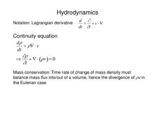
We find our motivation in astrophysical connections Ensman & Burrows ApJ92 • Radiative shocks have strongradiative energy transport that determines the shock structure • Exist throughout astrophysics SN 1987A Reighard PoP07 Cataclysmic binary star (see Krauland poster)
A brief primer on shock wave structure • Behind the shock, the faster sound waves connect the entire plasma Denser, Hotter unshocked shocked Shock velocity, us Initial plasma Mach number M > 1 Mach number M = us / csound
Shock waves become radiative when … • radiative energy flux would exceed incoming material energy flux where post-shock temperature is proportional to us2. • Setting these fluxes equal gives a threshold velocity of 60 km/s for our system: Ts4ous3/2 unshocked preheated shocked Material xenon gas Density 6.5 mg/cc Initial shock velocity 200 km/s Initial ion temperature 2 keV Typ. radiation temp. 50 eV
The CRASH project began with several elements • An experimental system that is challenging to model and relevant to NNSA, motivated by astrophysics • A 3D adaptive, well scaled, magnetohydrodynamic (MHD) code with a 15 year legacy and many users • A 3D deterministic radiative transfer code developed for parallel platforms • A strong V&V tradition with both codes • Some ideas about how to approach “UQ” in general and specifically the Assessment of Predictive Capability Space weather simulation
CRASH builds on a basic experiment • Basic Experiment: Radiography is the primary diagnostic. Additional data from other diagnostics. A. Reighard et al.Phys. Plas. 2006, 2007 F. Doss, et al. Phys. Plas. 2009, HEDP 2010 Grid Schematic of radiograph (see Doss poster)
What we predict • We predict scalar quantities • By predictive modeling we mean • computing an estimate of the probability distribution function (pdf) of the outputs generated by the pdf of the inputs for a prospective field experiment, informed by both simulation and prior field experiments • We predict the area where dense xenon exists on a radiograph and selected moments of the distribution of such locations • Holloway will show much more about this • Grosskopf has a poster on the integrated metrics What the radiograph fundamentally shows us is where dense Xe exists Grid
CRASH 2.1+ has substantial capability Material & AMR • Dynamic adaptive AMR • Level set interfaces • Self-consistent EOS and opacities for 5 materials • Multigroup-diffusion radiation transport • Electron physics and flux-limited electron heat conduction • Ongoing • Laser package • Multigroup preconditioner • I/O performance upgrade • Use of other EOS Log Density Log Electron Temperature Log Ion Temperature 3D Nozzle to Ellipse @ 13 ns
CRASH has proven useful • Design simulations of radiative reverse shock experiments • Simulations of ongoing NIF experiment • Simulations of x-ray driven radiative-shocks • We used CRASH to help select some details of the radiative reverse shock design (Krauland poster) x-ray driven radiative-shock (Myra poster)
Code improvements • Flux limited electron heat xport • EOS source adaptivity • Laser package • Progress on multigroup preconditioner • Hydro adjoint implementation • Reduced alchemy • Improved parallel I/O? • Vastly improved PDT scaling • Physics • Radtran & radhydro theory papers • X-ray driven walls theory • Further work on wall shock • Obtaining STA opacities • Work on non-LTE effects • SN/FLD comparison • Experiments • Shock breakout measurements • Initial attempts at other early time measurements • Late time (26 ns) measurements for predictive study • Radiograph analysis (compression, background) • UQ-driven planning for year-3 experiments • Metrology comparison We have accomplished a lot during the past year • UQ and predictive studies • Predictive study involving calibration • Two papers • Radiograph interpreter for integrated metrics • Deeper analysis of experimental and of all sources of uncertainty • Extensive studies of output sensitivity to code details • New tests • H2D 104 run set • Predictive study with calibration from H2D run set • Analysis of H2D limitations • 3D Hydro experiment design • CRASH 2.0 released and used • X-ray-driven modeling • Pure hydro nozzle study • Application to other experiments • Detailed examination of axial structures • Hydro instability studies Items in this color are directly responsive to 2009 review
Initializing CRASH with Hyades proved problematic • H2D has a laser package and (now) rezoner • Did run set for Dec 09 expt • Superseded by 104-run set done in early 2010 • This has produced results • But using Hyades has proven impractical • Rezoner had fidelity issues • Code revisions were slow • UQ was problematic • Results differ vs CRASH • H2D is manpower intensive • The rezoner works fine for typical design studies but not for predictive science • Comparison using 6 vs 3 zones in auto-rezoner: Decision: do a laser package in CRASH
The simulated morphological features were not useful for UQ • The CRASH code has yet to reliably produce the observed morphology in runs using Hyades initialization for laser drive Spring 2010 Fall 2010 Decisions: Focused effort for several months, then moved on; later improvements made a difference: see talk by Ken Powell 2. Adopted integrated metrics that are independent of morphological detail: see poster by Mike Grosskopf 3. Did predictive study with calibration using 1D simulations: see talk by James Holloway
Politics precluded integration of CRASH and PDT • One of the TST members indicated that at the labs the combined code would be considered UCNI • We sought a ruling, and what came out of DOE HQ was: “The final authority believes that the guidance is wrong and should be changed, but under current rules such a code would be UCNI” • We are told this will be addressed, “slowly” • This is despite the fact that several US universities and numerous foreign researchers are writing and even publishing codes with analogous capabilities. • Doing an UCNI code is for us a practical non-starter Decision: until this situation changes, we will pursue correlated studies to understand the impact of limited fidelity It might prove useful for the Review Team to make a very strong recommendation to DOE about addressing this
We are now ready for multi-D integrated studies • Our code is “good enough” and is getting better • We have carried out the UQ elements needed • The primary limitation going forward is computational • Details and implications to be discussed at length later • Includes core-hours limitations but also much more • Affects approach to UQ (following talks) • We intend to be the first academic team • to use statistical Assessment of Predictive Capability • to guide improvements in simulations and field experiments • that lead to predictions, known to have improved accuracy, of field experiments having extrapolated parameters (not physics) • and to demonstrate this by field measurements.
Our experimental sequence will improve and test our assessment of predictive capability • A conceptually simple experiment • Launch a Be plasma down a shock tube at ~ 200 km/s • Year 5 experiment • Predict outcome and accuracy before doing year 5 experiment • Goals • Improve predictive accuracy during project • Demonstrate a predictive uncertainty comparable to the observed experimental variability • A big challenge and achievement
Conservation of energy forces the shock wave to develop complex structure Shocked xenon layer Compressed 40x Traps thermal photons Preheated region Thermal photons escape upstream Other fun complications: Instabilities Wall shocks
Our experiments are at the Omega laser • Related experiments • LULI & PALS & RAL, LIL (soon?) • NIF & LMJ maybe someday One of our shots at the Omega laser • Omega • 60 beams • 30 kJ in 1 ns • 0.35 µm wavelength
How to produce radiative shocks • Laser beams launch Be piston into Xe or Ar gas at > 100 km/s • Piston drives shock • Diagnostics measure plasma properties • Gold grids provide spatial reference • Parameters • 1015 W/cm2 • 0.35 µm light • 1 ns pulse • 600 µm tube dia. Gas filled tubes Targets: KorbieKillebrew, Mike Grosskopf, Trisha Donajkowski, Donna Marion Experiments: Amy Reighard, Tony Visco, Forrest Doss
The laser first creates structure at the target surface • The laser is absorbed at less than 1% of solid density Ablation pressure from momentum balance: Typical pressures of tens of Mbars p ~ 8.6 I142/3 / µm2/3Mbars Radiative shocks need thinner targets than the one shown here From Drake, High-Energy-Density Physics, Springer (2006)
For radiative shocks, target acceleration produces the high required velocities Laser produced pressure accelerates Be plasma • Profiles at 1.3 ns shown Acceleration pushes velocity into radiative shock regime Expanding Be drives shock into Xe gas
Researchers are studying these shocks with a range of diagnostics and simulations • Radiographs Emission Interferometry Xray Thomson scattering Data credits: L. Boireau S. Bouquet, F. Doss M. Koenig, C. Michaut, A. Reighard, T. Visco , T. Vinci
Radiography is our workhorse; we also use other diagnostic methods X-ray Thomson Scattering Transverse Streaked Optical Pyrometer (SOP) UV Thomson Scattering Radiographs (1 or 2 views) Data by grad students Amy Reighard (Cooper), Tony Visco, Forrest Doss, Channing Huntington Christine Krauland Transverse VISAR
Lateral structure within the shocked layer is expected from a Vishniac-like mechanism. See E. Vishinac, ApJ 1983
Theoretical analysis shows structure internal to shocked layer for the experimental case • Wavelength and growth rate of instability in reasonable agreement with observations • Stereoscopic experiments will seek further evidence Unperturbed system Perturbed system Vorticity features Be Z = H . Shocked Xe U -Vs Z = 0 Vs Unshocked Xe Forrest Doss, et al. in preparation
Simulating these shocks is challenging but not impossible • Optically thin, large upstream • Electron heating by ions • Optically thin cooling layer • Optically thick downstream • This problem has • A large range of scales • Non-isotropic radiation • Complex hydro 20