Download
1 / 23
250 likes | 397 Views
REMOTE FIELD EDDY CURRENT MILITARY AND COMMERCIAL PLATFORM APPLICATIONS. Yushi Sun - Innovative Materials Testing Technologies, Inc. John C. Brausch, Kenneth LaCivita, Lt William Sanders - U. S. Air Force Research Laboratory. 1. Acknowledgements

E N D
REMOTE FIELD EDDY CURRENT MILITARY AND COMMERCIAL PLATFORM APPLICATIONS Yushi Sun - Innovative Materials Testing Technologies, Inc. John C. Brausch, Kenneth LaCivita, Lt William Sanders - U. S. Air Force Research Laboratory 1 Sun, Brausch, LaCivita and Sanders- 9th Joint FAA/DoD/NASA Conference on Aging Aircraft
Acknowledgements The authors would like to express their appreciation and great thanks to Jeff A. Register and Michael J, Fortman, Northwest Airlines[1], and Captain D. J. Butcher, Canadian Air Force, for their providing the test samples, test requirements and comments to IMTT. The authors would like also to express their appreciation and great thanks to Dr. Ward D. Rummel, D&W Enterprises, LTD, for his careful view and valuable comments to this paper. [1] Jeff A. Register and Michael J, Fortman were with Northwest Airlines when they were involved in the work, Application No. 6, stated in this paper. Now they are working with Aerotechinics NDT, Inc. Sun, Brausch, LaCivita and Sanders- 9th Joint FAA/DoD/NASA Conference on Aging Aircraft
Introduction • Current Tend of Utilizing Composite-Metal Structure in New & Old Airplanes • New Demand to NDT – Inspection of Metals through Composite • FG_RFEC Technique is Characterized by its Deep Penetration • Purpose of This Paper: • Introduce New Applications of FG_RFEC Technique in Inspection Metals Through Composite and others 2 Sun, Brausch, LaCivita and Sanders- 9th Joint FAA/DoD/NASA Conference on Aging Aircraft
Six Examples • Detection of aluminum layer crack through 1.5” of polycarbonate • Detection of aluminum layer crack through 0.52” – 0.90” graphite epoxy composite • Detection of titanium layer crack through 0.25” – 0.50” graphite epoxy composite • Detection of cracks on titanium layer through graphite epoxy composite and suppression of sealant groove signals • Detection of crack 0.50” below aluminum structure surface (simulating CC130 Structure) • Detection of fine surface and subsurface cracking on curved steel surface(Airbus A-320 Landing Gear Structure) 3 Sun, Brausch, LaCivita and Sanders- 9th Joint FAA/DoD/NASA Conference on Aging Aircraft
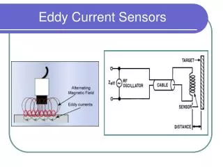
Probes 4 Sun, Brausch, LaCivita and Sanders- 9th Joint FAA/DoD/NASA Conference on Aging Aircraft
SSEC System 5 Sun, Brausch, LaCivita and Sanders- 9th Joint FAA/DoD/NASA Conference on Aging Aircraft
Example #1: Detection of aluminum layer crack through 1.5” of polycarbonate Three 7”×13” polycarbonate pieces with thicknesses: 567-007 – 0.567”; 483-007 – 0.483” 442-007 – 0.442” A 9.0”×1.25”×0.20” aluminum strip attached below One layer Two layers Three layers Aluminum Strip Probe Strip under inspection Probe Strip under inspection Probe 6 Sun, Brausch, LaCivita and Sanders- 9th Joint FAA/DoD/NASA Conference on Aging Aircraft
T = 0.567” T = 0.567” 7 Sun, Brausch, LaCivita and Sanders- 9th Joint FAA/DoD/NASA Conference on Aging Aircraft
8 Sun, Brausch, LaCivita and Sanders- 9th Joint FAA/DoD/NASA Conference on Aging Aircraft
Three Layers, T ~ 1.50” f = 200Hz Maximum Y = 0.1215v 9 Sun, Brausch, LaCivita and Sanders- 9th Joint FAA/DoD/NASA Conference on Aging Aircraft
Specimens T = 0.520” or 0.896” Example #2: Detection of aluminum layer crack through 0.52” – 0.90” graphite epoxy composite 10 Sun, Brausch, LaCivita and Sanders- 9th Joint FAA/DoD/NASA Conference on Aging Aircraft
T = 0.520” Set #1 Set #2 Sun, Brausch, LaCivita and Sanders- 9th Joint FAA/DoD/NASA Conference on Aging Aircraft
T = 0.896” Set #1 Set #2 Sun, Brausch, LaCivita and Sanders- 9th Joint FAA/DoD/NASA Conference on Aging Aircraft
Example #3: Detection of titanium layer crack through 0.25” – 0.50” graphite epoxy composite Specimens Crack sizes: 0.250”, 0.500” and 0.750” Composite Thickness: 0.250”, 0.333” and 0.500” Sun, Brausch, LaCivita and Sanders- 9th Joint FAA/DoD/NASA Conference on Aging Aircraft
Summary of Test Results With Composite Sample #2 Thickness = 0.250” With Composite Sample #3 Thickness = 0.334” With Composite Sample #4 Thickness = 0.500” Sun, Brausch, LaCivita and Sanders- 9th Joint FAA/DoD/NASA Conference on Aging Aircraft
Example #4: Detection of Ti layer crack through graphite epoxy composite and suppression of sealant groove signals Specimen Sun, Brausch, LaCivita and Sanders- 9th Joint FAA/DoD/NASA Conference on Aging Aircraft
Rotational Probe RF4 ROT Scanning around Fastener Sun, Brausch, LaCivita and Sanders- 9th Joint FAA/DoD/NASA Conference on Aging Aircraft
Case 1: Horizontal Groove is on top Pickup Case 2: Vertical Groove is on top Pickup Sun, Brausch, LaCivita and Sanders- 9th Joint FAA/DoD/NASA Conference on Aging Aircraft
Example # 5: Detection of crack 0.50” below aluminum structure surface Using Rotational Probe (CC130) Sun, Brausch, LaCivita and Sanders- 9th Joint FAA/DoD/NASA Conference on Aging Aircraft
Example #5: Detection of fine surface and subsurface cracking on curved steel surface (A-320 Landing Gear) 0.080” hidden hole drilled from top cut section 0.030”×0.030” upper EDM Possible crack area 0.030”×0.030” lower EDM Sun, Brausch, LaCivita and Sanders- 9th Joint FAA/DoD/NASA Conference on Aging Aircraft
Rf2 V.3 Sliding Probe + Specially Designed Holder Sun, Brausch, LaCivita and Sanders- 9th Joint FAA/DoD/NASA Conference on Aging Aircraft
Lower 0.030”×0.030” EDM F = 40.0 kHz Upper 0.030”×0.030” EDM F = 40.0 kHz Hidden hole F = 1.0 kHz Sun, Brausch, LaCivita and Sanders- 9th Joint FAA/DoD/NASA Conference on Aging Aircraft
Summary • Metallic layer cracks underneath thick composite layer are detectable using FG_RFEC technique – sliding probes or rotational probes; • Groove signal can be effectively suppressed using a band-pass filter; • FG_RFEC technique working with SSEC system is capable of detecting deeply hidden cracks and fine surface and subsurface cracking with high sensitivity. • The next step is to assess existing or new inspections, now available to our industry,to find the right fit and application of this advanced technology. Sun, Brausch, LaCivita and Sanders- 9th Joint FAA/DoD/NASA Conference on Aging Aircraft