Download
1 / 42
440 likes | 645 Views
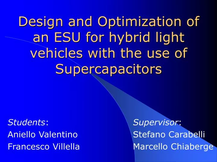
Design and Optimization of an ESU for hybrid light vehicles with the use of Supercapacitors. Students : Aniello Valentino Francesco Villella. Supervisor : Stefano Carabelli Marcello Chiaberge. Index. Introduction Supercapacitor ESU with Supercapacitors DC/DC Converter Modeling Results

E N D
Design and Optimization of an ESU for hybrid light vehicles with the use of Supercapacitors Students: Aniello Valentino Francesco Villella Supervisor: Stefano Carabelli Marcello Chiaberge
Index • Introduction • Supercapacitor • ESU with Supercapacitors • DC/DC Converter • Modeling • Results • Conclusions
Index • Introduction • Supercapacitor • ESU with Supercapacitors • DC/DC Converter • Modeling • Results • Conclusions
Introduction • Context • Motivations • Objectives
IntroductionContext Contex ESU with add-on Supercapacitors The Supercapacitors are an addition to batteries they can be inserted or excluded depending on the needs. TTW Three Tilting Wheels
IntroductionMotivations Motivations • Use supercapacitors in parallel with the battery to improve acceleration and energy recovery during braking • Designed for peak power requirements to increase the efficency and the life cycle of the ESU system • Feasibility study of an ESU Why Supercapacitors? The purpose is to allow higher accelerations and deceleration of the vehicle with minimal loss of energy, and conservation of the main battery pack.
Analysis and design of supercapacitor pack • Design procedure definition for supercaps • Analysis and design of supercap equalization net • Analysis and design of DC/DC converter • Definition of a dynamic model for supercap and DC/DC converter with several degrees of approximation IntroductionObjectives Objectives
Introduction • Supercapacitor • ESU with Supercapacitors • DC/DC Converter • Modeling • Results • Conclusions
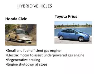
Supercapacitor Battery vs Supercap The non conventional batteries have High Power density but the charging time is high for this application.
Supercapacitor Supercapacitor DRAWBACKS • Low voltage for each cell • High Weight and Volume • Very expensive ADVANTAGES • High Capacitance and ultra low ESR • High Density of Power • Fast charging / discharging • High Available Current • High number of life cycles
Supercapacitor Equalization net In power applications, supercapacitors are used in stacks where many cells are connected in series or in parallel to obtain acceptable voltages and energy. • The disparities among the cell's parameters won't exhibit the same charging dynamic and, at end of charge transient, some cells may present over-voltage while some others are insufficiently charged. • The tolerance of the supercaps is 20%, but presumably if you buy supercaps from the same stock the tolerance reduces itself. • This involves the introduction of a control.
Supercapacitor Possible Solution DC/DC active solution Switched Resistor Integration Kit • ADVANTAGES : • High efficency • DRAWBACKS : • Several DC/DC converter • The implementation of the hardware and its control is very costly. • ADVANTAGES : • High efficency • User friendly • DRAWBACK : • Expensive 40$ • ADVANTAGES : • Simplest Solution • DRAWBACK : • Power loss
Index • Introduction • Supercapacitor • ESU with Supercapacitors • DC/DC Converter • Modeling • Results • Conclusions
ESU with Supercapacitor ESU with Supercapacitors ACTUAL SYSTEM PROPOSED SOLUTION • ADVANTAGES • In case of failure is always guaranteed connection between the battery and the inverter. • During braking, the controller decides which energy source recharge. • This power system allows acceleration and deceleration of the vehicle with minimal loss of energy and minimizes the stress of the batteries. DRAWBACK • We need to design a Bidirectional DC/DC converter. • ADVANTAGES • Simple realization DRAWBACKS • Great stress for battery • No longer battery life with high absorbed currents • Long charging time • Few charge-discharge cycles
Specifications Matlab Algorithm Results SC bank ESU with Supercapacitor Specifications • Ptraction = 22kW • Phase of Traction = 5 s • Phase of Braking = 10 s • Supercapacitor Add-on • ESU must be fault tolerant • Weight of ESU : less possible • Other important elements • Vbattery = 200V • Restriction of DC/DC converter
ESU with Supercapacitor Sizing supercapacitor bank • To respect the energy constraints, the physical limits of supercapacitors and the restrictions imposed by the DC/DC converter must be considered. • In our analysis the following issues have been taken into account: • Supercapacitor working voltage • Restriction of the DC/DC converter
ESU with Supercapacitor Supercapacitorworking voltage The working voltage of the supercaps must be lower than nominal voltage in order to lengthen life expectation. The aging processes of supercapacitors are mostly driven by temperature and cell voltage, which have an influence on the calendar life of the devices. 2,6V (96% of continuous voltage rating) was chosen because it is a voltage that ensures a sufficent life expectancy.
ESU with Supercapacitor Supercapacitor working voltage 1,3V (50% of continuous voltage rating) was chosen because it is a voltage that ensures a sufficient input voltage to the DC/DC converter and keeps the ratio max-input / min-input near 2. The discharge voltage ratio d (in %) of the supercapacitors bank is defined as: The DOD “Depth of Discharge” (in %) is then equal to: Then the Energy of Supercapacitor bank is given by the following equation: This equation shows that, for a 50% DOD, the useful energy represents 75% of the maximun energy. Is inefficent to discharge the bank below 50% of its max voltage.
ESU with Supercapacitor Restriction of the DC/DC converter The converter imposes constraints on the ratio between maximum input voltage and minimum input voltage, also between output voltage and input voltage. The restrictions refer to a non-isolated converter.
NO Initial conditionN=1 # SC in series=N Does the number of SC in series respect the costraint 5:1 ? processing YES Constraints DC/DC VinMAX Vinmin Calculate the energy of a module specifications Choose a model Needed Energy > E_module ? Needed Energy NO Add Module datasheet Add SC Repeat this procedure for all models and for 1<N<100 and Research the SC bank with minimum weight. YES save data Procedure
ESU with Supercapacitor Compromise Weight-Energy Result: The best compromise between weight and energy considering all the constraints on supercap and DC / DC converter has been found through a Matlab algorithm. • # cell in series (module): 35 • # module: 1 • # total of supercap : 35 • Input voltage range: 45,5÷91 V • Weight : 11,19 kg • Energy: 133087J 36,96Wh • Power:26.62kW for 5s • Volume : 9000 cm3 • Model:BCAP 1500
Index • Introduction • Supercapacitor • ESU with Supercapacitors • DC/DC Converter • Modeling • Results • Conclusions
DC/DC Converter DC/DC Bidirectional Converter It is necessary because the supercapacitorsvoltage (91V) is different in comparison to the DC BUS voltage (200V). Principle of Operation Constraints Constraint of application Weight application : less possible
DC/DC Converter Comparison isolated-non isolated • Two main categories of bidirectional DC/DC converters can be envisaged for this task: • Isolated converters • Full Bridge • Tapped Boost • Non isolated converters • Buck+Boost • Multiphase
DC/DC Converter Non isolated converters A variant of the Buck+Boost solution is the Multiphase Converter. • ADVANTAGES: • Simplest topology of the DC/DC converter • DRAWBACKS: • Excessive weight • Complicated Inductor costruction • ADVANTAGES: • The key principle of these converters is the output current sharing among several parallel channels. • DRAWBACK: • Interleaved strategy is very difficult.
Index • Introduction • Supercapacitor • ESU with Supercapacitors • DC/DC Converter • Modeling • Results • Conclusions
ESU Modeling ICE Electric motor Plant ACU Host Battery Supercap DC/DC Converter Power Module ECU System Modeling Modeling The modeling is needed to allow you to enter the ESU designed in the system. Virtual Prototype : Longitudinal dynamics model of the vehicle
Modeling Supercap Simulink Model Laboratory Test Analysis of results
Modeling DC/DC Converter + Supercap • FIRST APPROXIMATION • Assumptions: • Linearity • No losses (DC/DC) • Equations : • Buck eq. • Boost eq. • SECOND APPROXIMATION • Assumptions: • No Linearity, • Losses (DC/DC) • Equations : • State Equations(L,C)
Modeling Models Comparison • Comparison Parameters Assumptions for the buck phase (braking): • Static Simulations (fixed duty cycle) • Iniatial SC Voltage:60V • D = duty cycle = 40% T = Period = 20 us • Simulation time : 40s • In the first approx are visible only the mean values. • Very fast time simulation. • Simulation Time(40s) : 0,001s • In the second approx are visible the instantaneous values and you can see the voltage/current ripple. • Very long time simulation • Simulation Time(40s) : 30'
Modeling First vs Second approximation • If you need a fast simulation, and you do not want to see the transient then you can use the first approximation model. • If you want to see the current and voltage ripples you can use the second approximation model, this model is the most similar to the electric model. • For a more accurate comparison should have circuital simulations.
Modeling Dynamic Simulation • Real operating assumptions : • Dynamic Simulations (First approximation model with control) • Iniatial SC Voltage : 0V • D = duty cycle = variable T = Period = 20 us • Simulation time : 100s • C/!D = Charge/!Discharge = '1', after 40 s '0' • In the figure you can • see the possible real behaviour of the first approximation model. • Are visible the correct functioning of the system. • Very fast time simulation. • Simulation Time(100s): 0,001s
Index • Introduction • Supercapacitor • ESU with Supercapacitors • DC/DC Converter • Modeling • Results • Conlusions
Results Results The choices made concerning the following four points: • Topology • DC/DC Converter • SC Bank • Modeling
ResultsTopology Topology DC/DC converter with high voltage battery pack • In this solution we need to design only one bidirectional DC/DC converter. • Inserting an electronic switch in the converter it is possible to guarantee the safeness of the application. • The number of the supercap bank is not extreme. • The supercap bank is an add-on of the existing system.
Multiphase ResultsDC/DC Converter Bidirectional DC/DC Converter • The components are commercially available more easily • It is a direct converter then avoids losses related to the transformer
ResultsSC Bank Results Supercapacitor bank • Number of Scap = 35 • Type of Scap = BCAP1500 • Resulting Capacitance = 42,85F • Resulting ESR = 16,45mΩ • Energy storage=133087 J 36,97Wh • Volume = 9000cm3 • Cost Scaps = 2750 dollars • Weight Scaps = 11,19 Kg • Estimated weight DC/DC converter 22 Kg • Max weight battery = 20 Kg • Estimated weight ESU 53Kg • Estimated operating temperature -25 ÷ 70 °C
ResultsModeling ESU Model • The first approximation model is a simple solution and has a short time simulation, in the future it will be placed in the Virtual Prototype. • It will be used to evaluate the performance of the vehicle with and without the use of the supercapacitors.
Index • Introduction • Supercapacitor • ESU with Supercapacitors • DC/DC Converter • Modeling • Results • Conclusions
In conclusion, for the requested application, the resulting data are excessive in terms of weight and volume occupied. However, to confirm these conclusions, it would be interesting being able to perform tests, using the simulator. They will produce curves that may highlight the performance gap with and without the ESU. Conclusions • Very high cost (Supercap + DC/DC Conv.) • High weight and volume (Supercap + DC/DC Conv.)
Conclusions The supercaps are suitable to be used either in buses, trains, trolley buses... ...or in high performance vehicles, such as sport cars and competition motorcycles.
Thanks Aniello Valentino – Francesco Villella