Download
1 / 12
120 likes | 335 Views
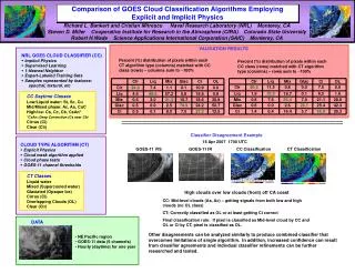
Comparison of compressible explicit density-based and implicit pressure-based CFD methods for the simulation of cavitating flows. Romuald Skoda. Uwe Iben. Martin Güntner, Rudolf Schilling. Motivation.

E N D
Comparison of compressible explicit density-based and implicit pressure-based CFD methods for the simulation of cavitating flows Romuald Skoda Uwe Iben Martin Güntner, Rudolf Schilling
Motivation Explict CFD methodsresolveall relevant time scalesofthewavedynamics (~ 1 nano sec). Problem: Due tothecouplingofspatialandtemporal resolution (accoustic CFL condition) explicit methodsgenerateprohibitelylongcomputationtimes in complex geometries (injectionsystems, pumps, …) Isitreallynecessarytoresolve all time scales? Wewouldliketoincreasethe time stepsystematicallyandthereforeneed an implicitmethod. Cavitating flow in a micro channel Skoda, Iben, Morozov, Mihatsch, Schmidt, Adams: Warwick, UK, 2011 Liquid Volume fraction Pressure Distanceof Wave travelat CFL = 1 The smallestcell in thedomaindictatestheoverall time step
NumericalmethodandPhysicalmodel Toget an implictmethodwemodifya compressiblestandardpressure-basedalgorithm (SIMPLE, 2. order in spaceand time) 1.) localunderrelaxation (preconditioningofthematrix) 2.) density- insteadofpressurecorrection, pressurefromEOS Reference method: Explicit density-based code with CATUM flux functions (TU Munich) and time integration scheme (2. order) Homogenousmodel Neglect of the energy equation and use of a barotropicEOS inviscidflow
Non-CavitatingRiemann problem (CFL = 1) Temporal pressuredevelopmentfor100 bar / 1 bar Explicit2. Order Implicit 2. Order in Space 1. Order in Time p [Pa] p [Pa] x [m] x [m] 1 2 3 4 Time instant WiththeImplicitmethod, wecanreproducethe Explicit methodresults.
Cavitating Riemann problem (CFL = 1) Temporal pressuredevelopmentfor1 bar / 0.073 bar Explicit2. Order Implicit 2. Order in Space 1. Order in Time p [Pa] p [Pa] Two-phase flow x [m] x [m] 1 2 3 4 Time instant WiththeImplicitmethod, wecanreproducethe Explicit methodresults. Conclusion: The Implicitschemeisfeasible.Forthenexttestcase, weusea secondorder in time andspace.
NACA profile Computationalsetup • Re = 1.56 e5 • a = 6° Instantaneousresults Vapour Volume Fraction Pressure Periodicsheddingandre-entrantjet Shock wave
Explicit vsimplicitmethodat CFL = 2 Temporal developmentofthe wall pressure Erosion probability THR = 5 bar PP [-] p [Pa] Statistical evaluation (threshold) ExplicitImplicit t [ms] Co-ordinate salongsuctionsurface 10*s [m] Analysis interval s The Explicit andImplicitmethodsyieldsimilarresults. s=0
Increaseofthe CFL number Integral Vapour Volume Fraction CFL = 2 CFL = 20 CFL = 200 CFL = 2000 Integral vapourVF[-] t [sec] t [sec] t [sec] t [sec] Nosignificantinfluenceofthe CFL number.
Maximum pressureatsuctionsurface Maximum pressureon thesuctionsuface in theanalysis time interval pMax [Pa] CFL = 2 CFL = 20 CFL = 200 CFL = 2000 10*s [m] Co-ordinate salongsuctionside Pressurepeaksgetlowerwithincreasing CFL number.Conclusion: thethresholdforthestatisticalevaluation must not betoo high.
Erosion probability Wall loadatsuctionsurface PP [-] THR = 1.5 bar CFL = 2CFL = 20CFL = 200CFL = 2000 Co-ordinate salongsuctionside 10*s [m] Forhigher CFL-number, thesolutiontendencyismaintained.
Applicationto a microchannelflow Hight: 100 mm Length: 1000 mm Inletpressurepin = 300 bar Variation oftheoutletpressure pout = 80 barpout = 125 barpout = 160 bar Explicit CFL = 1 Implicit CFL = 100 Pp [-] Pp [-] THR = 250 bar THR = 250 bar Erosion probability Erosion probability Channel length [-] Channel length [-]
Conclusions Forthepredictionofthewall loadwhichistheoriginofcavitationerosionitissufficienttouseCFL ~ 100. Possibleapplication: visousflowcomputationswith a finenear-wall resolution. The pressure-basedcodehas in total a muchhigher CPU time thanthe explicit code due tonumericalissues. The cost per time step must bedecreased. Forfutureinvestigationswerecommendtouseimplicitdensity-basedmethods.