Download
1 / 24
240 likes | 342 Views
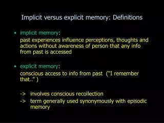
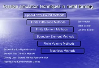
Possible simulation techniques in metal forming. Satic Implicit Static Explicit Dynamic Explicit. Smooth Particle Hydrodynamics Element Free Galerkin Method Moving Least Square Method Approximation Reproducing Kernel Particle Method. Modular Structure of Forming Processes.

E N D
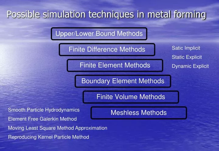
Possible simulation techniques in metal forming Satic Implicit Static Explicit Dynamic Explicit SmoothParticle Hydrodynamics Element Free Galerkin Method Moving Least Square Method Approximation Reproducing Kernel Particle Method
Modular Structure of Forming Processes reference: K. Lange, Stuttgart
Commercially available FE programs for forming process simulation
Topics • Why Forging Simulation?
Conventional Product Development Customer Specs Prototype Testing Mass Production Design & Tool Dev. Pilot Stage • Expensive Fixes: • visible defects • press capacity exceeded • underfilling (drop forging) • high localized die loads • More Expensive Fixes: • “invisible” defects • unacceptable tolerances • Most Expensive Fixes: • short die life • unstable process conditions Reduce ‘s, improve time to market !
simulation Customer Specs Prototype Testing Prototype Testing Mass Production Mass Production Design & Tool Dev. Pilot Stage Pilot Stage • Shorter Development Time: • less trial and error • less blocking of production line • optimized for available press • less visible defects • Less Fine Tuning: • improved quality • less invisible defects Mass Production Pilot Stage time to market shorter time to market Simulation-Aided Product Development Be First to Market with Better and Cheaper Products !
simulation Customer Specs Prototype Testing Mass Production Design & Tool Dev. Pilot Stage • Optimization during product life time: • extend die life • minimize material scrap • optimize process conditions • optimize press capacity utilization Additional Benefits of Simulation • Other benefits: • reduce number of mfg stages • more insight into mfg process • less machining operations • expand state of the art • more successful bids Reduce Costs during Mass Production !
Why Simulation • Reduce Time to Market • Reduce Cost of Tool Development • Predict Influence of Process Parameters • Reduce Productions Cost • Improve Product Quality • Better Understanding of Material Behavior • Reduce Material Waste
Manufacturing Results • Accurately predict the material flow • Determine degree of filling of the swage or die • Accurate assessment of net shape • Predict if laps or other defects exist • Determine the stresses, temperatures, and residual stresses in the work piece. • Determine optimal shape of preform
Material Behavior • Determine material properties such as grain size • Determine local hardness • Predict material damage • Predict phase changes and composition • Simulate the influence of material selection
Tool Results • Determine the forming loads • Determine the stresses in the tools • Evaluate tool wear or fatigue • Simulate the influence of lubrication • Optimize multi-tool process
Simulation allows you to capture behavior that can not be readily measured – providing deeper insight into your manufacturing processes
Damage Prediction - Chevroning Multi-stage Hydraulic Press with Annealing Transfer Press
Possible forming of laps and its prediction through simulation technique
Kinematics • Placing the workpiece • Closing the tools • Forming process • Removal of the tools • Extraction of the workpiece • Including spring-back • Subsequent cool-down
Flexible Tool Definition • Rigid Tools • Deformable • Direct CAD NURB Description
Material Models • Power Laws • Johnson-Cook • Kumar • Grain Size Prediction • Phase Changes • Elastic Plastic • Rigid Plastic • Material Database • Isotropic hardening • Cowper-Symonds
Effects of Elasticity • Elasticity of Tools • Prestressed Dies • Residual Stresses • Behavior of part during ejection or removal • Determination of tolerances
Friction • Friction Influences: • load and energy requirements • metal flow • pressure distribution • die wear • Friction Models • Coulomb friction • plastic shear friction • combination • User-extendable Database
Visualization • Tracking of Material Particles • Flow Line Images • Time History of Tool Forces • Deformation of Workpiece • Contour Plots of all Quantities
Material Cost Savings The cost of NOT doing it right the first time?