Download
1 / 27
280 likes | 428 Views
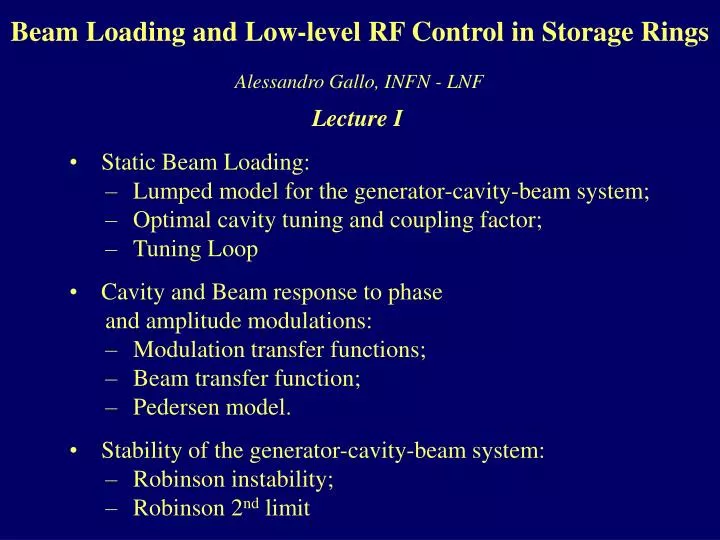
Beam Loading and Low-level RF Control in Storage Rings. Alessandro Gallo, INFN - LNF. Lecture I. Static Beam Loading: Lumped model for the generator-cavity-beam system; Optimal cavity tuning and coupling factor; Tuning Loop Cavity and Beam response to phase

E N D
Beam Loading and Low-level RF Controlin Storage Rings Alessandro Gallo, INFN - LNF Lecture I • Static Beam Loading: • Lumped model for the generator-cavity-beam system; • Optimal cavity tuning and coupling factor; • Tuning Loop • Cavity and Beam response to phase • and amplitude modulations: • Modulation transfer functions; • Beam transfer function; • Pedersen model. • Stability of the generator-cavity-beam system: • Robinson instability; • Robinson 2nd limit
STATIC BEAM LOADING We know from the longitudinal dynamics theory of storage rings that the motion of a single particle is stably focused around an equilibrium position known as “synchronous phase”. The synchronous phase corresponds to an accelerating voltage on the particle equal to its average single-turn loss, which accounts for synchrotron radiation emission and interaction with the vacuum chamber wakefields. In synchrotrons this also accounts for the required energy gain/turn during ramping. For storage rings with positive dilation factor the synchronous phase is placed on the accelerating voltage positive slope; the contrary for negative dilation factor rings. The particle absorbs energy from the accelerating field but also contributes to the total voltage. The particle induced voltage can be easily calculated treating the cavity accelerating mode as a lumped resonant RLC resonator interacting with an impulsive current.
THE CAVITY RLC MODEL The beam-cavity interaction can be conveniently described by introducing the resonator RLC model. According to this model, the cavity fundamental mode interacts with the beam current just like a parallel RLC lumped resonator. The relations between the RLC model parameters and the mode field integrals wr (mode angular resonant frequency), Vc(maximum voltage gain for a particle travelling along the cavity gap for a given field level), U (energy stored in the mode), Pd (average power dissipated on the cavity walls) and Q (mode quality factor), are given by:
A particle travelling along the cavity gap is a d-function current generator exciting the RLC resonator. The particle induced voltage in the cavity vq(t) is a decaying cosine wave generated at the particle passage. The fundamental theorem of beam loading states that the particle “sees” only half of its induced voltage step DVq. According to the model, the expression for vq(t) is: The particle in a storage ring are gathered in bunches that typically show a gaussian longitudinal profile. The bunches are normally much shorter than the RF wavelength and interact with the accelerating field similarly to macroparticles. The voltage induced in the cavity by a short gaussian bunch is still an exponentially decaying cosine wave with a finite rise time (related to the bunch duration). STATIC BEAM LOADING
STATIC BEAM LOADING It can be easily verified that both the amplitude and the slope of the voltage induced in a cavity by a single passage of a short bunch are almost negligible with respect to the cavity accelerating voltage. What can not in general be neglected is the voltage generated by the cumulative effect of many bunch passages. In fact, the time distance between adjacent bunches is normally much smaller than the cavity filling time. This is true even in single bunch operation whenever the ring revolution period is smaller than the cavity filling time. In this case the voltage kicks associated to the passage of the bunches add coherently, and the overall beam induced voltage can grow substantially and even exceed the generator induced voltage.
STATIC BEAM LOADING The cumulative contribution of many bunch passages depends essentially on the RF harmonic of the beam spectrum. Also neighbour lines play a role in case of uneven bunch filling pattern (gap transient effect). • The static beam loading problem consists in computing: • the overall contribution of the beam to the accelerating voltage; • the power needed from the RF generator to refurnish both cavity and beam; • the optimal values of cavity detuning and cavity- to-generator coupling to minimize the power request to the generator.
STATIC BEAM LOADING To solve the static beam loading problem we refer to the following circuital model: The beam current is represented by the phasor Ib at the frequency of the RF source, while the external RF source is represented by a current generator Ig whose amplitude is related to the power of the forward wave launched on the transmission line. If h>0 the beam current phasor anticipates the total cavity voltage (i.e. fs >0), while it is retarded in the opposite case (h<0fs <0 ). The RF sources are normally specified by the maximum amount of power deliverable on a matched load. This is also the power actually dissipated in the system whenever a circulator is interposed to protect and match the source. The cavity is usually tuned near the optimal value that minimizes the request of forward RF power to the generator.
STATIC BEAM LOADING The analysis of the beam-cavity circuital model leads to the reported phasor diagram. The total current exciting the cavity is: It may be noticed that only the imaginary part of the total current does depend on the cavity tuning. Real and imaginary parts of the generator current are then given by: Being the off-resonance parameter d defined as : the minimum amplitude of the generator current phasor isobtained when its imaginary part is zero. The optimal cavity tuning condition is therefore given by:
h < 0 h > 0 STATIC BEAM LOADING The optimal cavity tuning condition in a storage ring with negative dilation factor h asks for positive values of d. This means that the cavity has to be tuned below the frequency of the RF generator, and the amount of detuning is proportional to the intensity of the stored current. The sign of the detuning is just opposite for positive values of the dilation factor h. Under the optimal cavity tuning condition we also have: leading to the optimal coupling condition: It follows immediately that the forward power request to the external generator is: The system is perfectly matched and no RF power is wasted because of reflections.
Zero for optimal coupling factor Zero for optimal cavity detuning STATIC BEAM LOADING The beam can be also modelled as a complex admittance equal to the ratio between the current and voltage phasors. This model is less physical (the resistive part of the beam admittance does not enlarge the bandwidth of the cavity!) but allows more direct computation of the reflection coefficient at the coupling port.
STATIC BEAM LOADING For a given required cavity voltage Vc, the optimal values of the cavity detuning d and coupling coefficient b are both dependent on the instantaneous stored current Ib. The accelerating cavities are equipped with tuners, that are devices allowing small and continuous cavity profile deformation to real time control the resonant frequency position. Sometimes cavities are also equipped with variable input couplers but they are never operated in regime of continuous b adjustment. In general the coupling coefficient is adjusted just once to match the maximum expected beam current. At lower currents the system is partially mismatched, but the available RF power is nevertheless sufficient to feed the cavity and the beam. It turns out that the cavity tuning d and the generator power PFWD have to follow the actual current value in order to keep the accelerating voltage constant preserving good matching conditions. These tasks are normally accomplished by dedicated slow feedback systems, namely the “tuning loop” and the “amplitude loop”.
Beam with TUNING LOOP The tuning loop restores automatically and continuously the cavity resonant frequency to compensate the beam reactive admittance. The loop controls the RF phase between the cavity voltage and the forward wave from the generator. Phase drifts are corrected by producing mechanical deformations of the cavity profile by means of dedicated devices (plungers, squeezers, ...). In fact the loop controls the phase of the transfer function: By controlling the set point of the variable phase shifter the phase of the transfer function can be locked to 0 or to any other value f0.
The reflection at the input coupler port is not minimized in this case, and the overall efficiency of the system is reduced. TUNING LOOP The best cavity tuning is obtained by locking the loop to f0 = 0. In this case we have: For dynamics considerations, sometimes it is useful to set a phase f0 slightly different from zero. In this case we have: Tuning loops are generally very slow since they involve mechanical movimentation through the action of motors. Typical bandwidth of such systems are of the order of 1 Hz. Tuning systems are also necessary to stabilize the cavity resonance against thermal drifts.
Cavity and Beamresponse to phase and • amplitude modulations
CAVITY RESPONSE to AM and PM SIGNALS Servo-loops and feedback loops apply AM and PM modulation to the cavity. If the cavity is detuned the modulating signals are filtered and mixed by the cavity frequency response: It may be demonstrated that direct and cross modulation transfer functions are given by:
CAVITY RESPONSE to AM and PM SIGNALS Being the cavity impedance in the Laplace domain expressed by: where fz=-fy is the phase of the cavity impedance at the generator frequency w, one gets: The general form of the modulation transfer functions features 2 poles (possibly a complex conjugate pair) and 1 zero, and degenerate to a single pole LPF response if the cavity is perfectly tuned (cross modulation terms vanish in this case).
similar expressions CAVITY RESPONSE to AM and PM SIGNALS Since the total current IT is the vector difference of the two currents Ig and Ib, the final modulation transfer function from Igand Ib to the cavity voltage Vc are given by:
CAVITY RESPONSE to AM and PM SIGNALS The complete expressions for the modulation transfer functions can be worked out with some algebra and result to be: The beam, with the uncommon exception of bunch length comparable with the RF wavelength, can only exhibit phase modulation (the amplitude of the beam spectrum line at the generator frequency is fixed and equal to 2qb/Tb).
Beam Transfer Function Let’s consider the synchrotron motion fb(t) of a particle in a storage ring where the accelerating voltage is not modulated (i.e. fc(t)=fclock , being fb(t) measured respect to the same fclock). The synchrotron equation has the form: where a accounts for frictional terms which may damp or amplify the oscillations. If the cavity phase fc(t) is modulated the synchrotron equation becomes (neglecting a ): The “Beam transfer function” B(s) measures the response of the beam to a cavity phase modulation in the Laplace s-domain. The response is one-to-one at dc (the beam follows the slow phase motion of the cavity) and peaks at the synchrotron frequency (infinitely if no damping is provided). The function B(s) represents the forward block in the active feedback systems aimed at generating some damping term ato stabilize the beam. The beam phase also depends on the cavity voltage amplitude, according to:
Generator Cavity Beam + p p p + a a + a CAVITY RESPONSE to AM and PM SIGNALS: PEDERSEN MODEL The whole generator-cavity-beam system can be graphically represented in a diagram called Pedersen Model. The modulation transfer functions vary with the stored current and definitely couple the servo-loops and the beam loops implemented around the system.
The zeros of this equation must have negative real part to avoid system instability. If the equation is put in polynomial form we must have: Stability of the System without Loops Even if no AM and PM are applied from the generator (no loops acting on the system), still there is an intrinsic loop from cavity to beam and backward. The stability of the system can be derived from the characteristic equation: These conditions are fulfilled if the two following relations are satisfied: These are the Robinson instability limits and are predicted in the identical form by the theory of the longitudinal coupled bunched instabilities applied to the beam barycentre motion ( CB mode “0”, all bunches in phase).
The 1stRobinson condition states that the beam is stable at positive h if the upper synchrotron sideband samples a larger cavity resistive impedance with respect to the lower synchrotron sideband (the opposite for negative h). h >0 => unstable h <0 => stable h >0 => stable h <0 => unstable w + ws w - ws w - ws w + ws The damping constant aR is given by: The condition aR> 0 (beam stability) is immediately satisfied if This is not a primiry issue since the beam loading detunes the cavity in the direction where Robinson damping is generated. Stability of the System without Loops The Robinson 2nd limit can be also derived from the bunched beam coherent instabilities theory. The coherent frequency of the barycentre motion of the bunches wsc is given by: and the Robinson 2nd limit is reached when wsc gets to zero, i.e. :
Robinson 2nd limit Stability of the System without Loops The Robinson 2nd limit has also another important interpretation. From the phasor diagram the following general relations can be derived: The portion of the cavity voltage induced by the external generator is the phasor Vg=ZLIg. The phase of Vg relative to Ig is fz . At the 2nd Robinson limit the absolute phase of Vg is fg+fz = fs which means that the beam is on the crest of Vg . For the barycentre coherent motion only Vg provides longitudinal focusing since the beam induced voltage simply follows the bunches and does not contribute to the restoring force. At the Robinson 2nd limit there is no residual focusing for the coherent synchrotron oscillation and the beam is suddenly lost.
Overvoltage factor Stability of the System without Loops For an optimally tuned cavity the 2nd Robinson limit appears at the threshold: In the optimal tuning case, the Robinson 2nd limit in terms of current gives: which means that the limit is reached beyond the current value Ib-opt matching the input coupling. However, getting close to the 2nd Robinson limit the coherent frequency of mode 0 can be very low. The motion of the bunches gets very sensitive to the low frequency noise in the RF systems, and some beam feedback systems designed for the nominal synchrotron frequency can work improperly. Feed-forward and direct RF feedback systems can be implemented to avoid such effect. It can be demonstrated that the 2nd Robinson limit can be avoided also by moving from the optimal tuning condition adding some extra tuning f0 to the system. The coherent frequency of mode 0 does not get to zero in this case but tends lowering to an asymptotic non-zero value. However, this cure has a cost in terms of RF power reflected from the cavity coupler and require therefore oversized RF power sources.