Download

1 / 41
530 likes | 1.61k Views
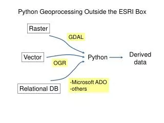
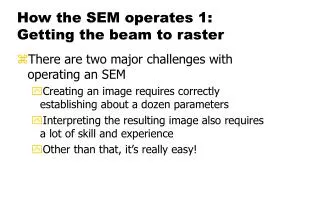
How the SEM operates 1: Getting the beam to raster . There are two major challenges with operating an SEM Creating an image requires correctly establishing about a dozen parameters Interpreting the resulting image also requires a lot of skill and experience Other than that, it’s really easy!.

E N D
How the SEM operates 1:Getting the beam to raster • There are two major challenges with operating an SEM • Creating an image requires correctly establishing about a dozen parameters • Interpreting the resulting image also requires a lot of skill and experience • Other than that, it’s really easy!
Imaging Inputs (operator controls) 20 25 200 15 100 40 40 60 60 500 10 30 50 80 80 20 20 5 100 100 35 1000 0 0 10 1 brightness kV probe current contrast 25 1,000 10,000 24 45 20 30 15 35 100,000 6 90 100 Everhart-ThornleyThrough the Lens (TTL) LowVac vCD/4QBS Helix 10 40 1,000,000 180 1.6 5 10 working distance magnification dwell time Slide stolen from Charles Lyman (with many changes) detector choice
C1 lens current Schematic drawing of scanning electron microscope Raster beam Determine magnification C3 lens current
Everhart-Thornley detector (1960)
All slides with the yellow graphic are courtesy of David Joy, U of Tennessee David Joy probably knows more about electron microscopy than anyone else alive Where the credit belongs Intro to Hi Performance SEM
Imaging modes • Resolution: gives maximum resolution! • High current: for optimum contrast, EDX and EBSD • Depth of focus: large depth of field is a great attribute of the SEM. Use long working distance • Low voltage mode • Better topographic information • Ability to overcome charging Intro to Hi Performance SEM
Accelerating potential: V0 Probe current: Ip Beam diameter: dp Convergence angle: αp Parameters Determining Resolution Intro to Hi Performance SEM
Currents in an SEM (W-filament) • Filament current: Current that heats a tungsten filament, typically 2.6-2.8 A. Strongly affects filament lifetime. Similar for Schottky FEG, but only heated to 1700 K • Emission current: total current leaving the filament, typically about 400 μA for W-filament, 40 μA for FEG. • Beam current: Portion of emission current that transits the anode aperture; decreases going down the column. • Probe current: a calculated number related to the current on the sample, typically 10 pA – 1 nA. • Specimen current: the current leaving the sample through the stage, typically about 10% of the probe current. Remember that one electron incident on the sample can generate many in the sample…a 20 keV electron can generate hundreds at 5 eV. • FEI also defines a parameter called “spot size” which is proportional to the log2(probe current); proportionality constant depends on aperture size.
Electron sources/guns: options • The requirements for modern SEMs call for nanometer resolution, high current into small probe sizes, and effective low voltage operation • Such needs make the venerable thermionic gun obsolete for top of the line SEMs • So all high performance SEMs now use some more advanced form of electron source • W-filament machines are still much less expensive and adequate for many applications Intro to Hi Performance SEM
When do we need which kind of SEM? • The FEG SEM offers high performance not just high resolution • This means large probe currents (up to a few nanoamps, [Ip in Leo goes to 5 μA] important for EDS and EBSD), and small diameter electron probes (from 1 to 3nm), over a wide energy range (from 0.5 -30keV). • The FEG SEM performance package involves both the gun and the probe forming lenses • Huge difference in resolution between FEG and W-filament at very low voltage • A FEG SEM will cost about twice as much as a W-filament machine! Intro to Hi Performance SEM
Tungsten Hairpin Filaments • The electron source is the key to overall performance • The long time source of choice has been the W hairpin source • Boils electrons over the top of the energy barrier - the current density Jc depends on the temperature and the cathode work function f- Richardson’s equation….. Jc=AT2exp(-e/kT) • Cheap to make and use ($12.58 ea) and only a modest vacuum is required. No vac-ion pump. Last tens of hours. Thermionic electrons Schematic Model of Thermionic Emission Intro to Hi Performance SEM
Cold Field Emitters (FEG) • Electrons ‘tunnel out’ from a tungsten wire because of the high field obtained by using a sharp tip (100nm) and a high voltage (3-4kV) Jc=AF2/.exp(-B1.5/ F) • The Fowler-Nordheim equation shows that the output is temperature independent – hence the name ‘cold’ • Needs UHV but gives long life and high performance Intro to Hi Performance SEM
Flashing: required of cold-FEGs, not Schottky thermal field emitters • Each tip should show a consistent emission current when it is flashed • Compare the tip current with its own usual value not with that from other tips • If the value is low, flash several times until the current recovers • Excessive flashing may blunt the tip
Cold FEG Gun behavior • (Hitachi and JEOL make cold-FEG microscopes) • The tip must be atomically clean to perform properly as a field emitter • Even at 10-6 Torr a monolayer (“one Langmuir”) of gas is deposited in just 1 sec so the tip must be cleaned every time before it is used; tip needs 10-10 Torr • Cleaning is performed by ‘flashing’ - heating the tip to white heat for a few seconds. This burns off (desorbs) the gas Intro to Hi Performance SEM
Typical characteristics • The tip is usually covered with a mono- layer of gas after 5-10 minutes • The emission then stabilizes for a period of from 2 hours (new machine) to 8 hours (mature machine). • On the Hitachi S4700, S4800, and S5500 the tip must be re-flashed after 8-12 hours of operation (the machine gives you a warning) • On the plateau region the total noise + drift is only a few percent over any period of a few minutes…not particularly stable. Intro to Hi Performance SEM
Schottky Emitters • In the Schottky emitter the field F reduces the work function f by an amount - Df = 3.80E-4 F1/2eV • Cathode behaves like a thermionic emitter with f* = f-Df • The cathode is also enhanced by adding ZrO2 to lower the value of f • Lifetime ~ 2 years kept hot and running 24/7 Df ZrO2 dispenser Schottky Emission Intro to Hi Performance SEM
The Schottky Emitter • The Schottky source runs at ~1750K • It is not a field emitter – despite what other companies tell you - because the tip is blunt and if the heat is turned off there is no emission current • A Schottky is aField Assisted Thermionic Source Hitachi Schottky Emitter Tip Intro to Hi Performance SEM
Schottky Performance • Schottky emitters can produce large amounts of current compared to cold FEG systems; cold FEGs are less useful for EDS and useless for e-beam lithography. • Because they are always on they are very stable (few % per week change in current) • They eventually fail when the Zirconia reservoir is depleted: 1-2 years. Intro to Hi Performance SEM Output from Schottky gun
Nano tips - atomic sized FEG • Nano-tips are field emitters in which the size of the tip has shrunk to a single atom. • They can be made by processing normal tungsten FE tips • More usually they are made from carbon nanotubes • They can operate at energies as low as 50eV, and have a very small source size Etched tungsten tip Field ion image of a W nanotip emitter Intro to Hi Performance SEM
Regular and Nano Tips Nano tip Regular tip Copper alignment grid sample in S6000 CD-SEM Courtesy A. Vladar, NIST Intro to Hi Performance SEM
The source size is apparent width of the disc from which the electrons appear to come Small is good- for high resolution SEM because less demagnification is needed to attain a given probe size But too small may be bad – because demagnification helps minimize the effects of vibration and fields W hairpin- 50µm Schottky - 25nm Cold FEG - 5nm Nano-FEG - 0.5nm (1) Source Size The physical size of the tip does not determine the source size! Intro to Hi Performance SEM
How to choose? • How can we choose between these different electron sources? • Usually compare three parameters of performance-size, brightness, energy spread • But other issues – such as the COST, the vacuum system required, and the desired APPLICATION – are of paramount importance so the best choice may still be the tungsten hairpin Intro to Hi Performance SEM
Brightness • Luminance is a photometric measure of the density of luminous intensity in a given direction. It describes the amount of light that passes through or is emitted from a particular area, and falls within a given solid angle. “Brightness” is a term which has been supplanted by “luminance”. • Lv = d2F/(dA dΩ cosθ) • Where: • Lv is the luminance or brightness • F is the flux of radiation or electrons • dA is the area on the source or detector • dΩ is the solid angle subtended by the detector • Θ is the angle between the direction the radiation is going and the normal to the detector area
(2) Source Brightness • Brightness current per unit area per solid angle;has units of amp/cm2/steradian • Brightness is conserved Also increases linearly with voltage Measuring b at the specimen Intro to Hi Performance SEM
Conservation of brightness Strong condenser lens: Smaller beam area Tighter focus More electrons apertured Out by final aperture Weak condenser lens: Larger beam area Less tight focus Fewer electrons apertured out by aperture Sample
Brightness is the most useful measure of gun performance Brightness varies linearly with energy one so must compare different guns at the same beam energy High brightness is not the same as high current At 20keV typical values (A/cm2/str) W hairpin 105 FEGs 108 nano-FEG 1010 Emitter brightness Intro to Hi Performance SEM
(3) Energy Spread • Electrons leave guns with an energy spread that depends on the cathode type • Lens focus varies with energy (chromatic aberration) so a high energy spread hurts high resolution,low energy images • The energy spread of a W thermionic emitter is about 2.5eV, and 1eV for LaB6 • For field emitters the energy spread varies with temperature and mode of use 0.7eV 1.5eV 0.3eV Intro to Hi Performance SEM
Summary • The cold FEG offers high brightness, small size and low energy spread, but is least stable, generates limited current and must be flashed daily. • But Schottky emitters are stable, reliable, and have most the best features of cold FEG and the familiar tungsten hairpin source • Nanotips may be the source of the future if the bugs can be worked out • W-hairpins are adequate for many applications not demanding highest resolution. Intro to Hi Performance SEM
Lenses • A lens forms an Image of an Object • Visual optics are made of glass which refracts light and have a fixed focal length • Electron-optical lenses employ magnetic or electrostatic fields as the refracting medium • The focal length f can be changed by varying the lens excitation (the current or the potential) Thin lens equations Intro to Hi Performance SEM
Hitachi’s view of Practical electron lenses… • The most common electron lens is a horseshoe magnet • The field across the gap focuses a beam of electrons passing through it • The basic practical form of this lens rolls it into a cylinder • Real lenses come in several various forms. . . . Snorkel lens Immersion lens Intro to Hi Performance SEM
Another view of lenses Intro to Hi Performance SEM
The ideal lens Ray tracing computation of probe profile • The ideal lens would produce a demagnified copy of the electron source at its focus • The size of this spot could be made as small as desired • But no real lens is perfect (or even close) 10% max. Probe diameter 10A Intro to Hi Performance SEM
Spherical Aberration • The focal length of near axis electrons is longer than that of off axis electrons • All lenses have spherical aberration -minimum spot size dmin = 0.5Csa3 • Cs is a lens constant equal to the working distance of the lens • n.b.: minimizing working distance minimizes spherical aberration • Spherical aberration makes the probe larger, degrades the beam profile, and limits the numerical aperture (a) of the probe lens. This reduces the current IB which varies as a2 a DOLC Gaussian Focus plane Intro to Hi Performance SEM
Stigmation: correction for spherical aberrations Intro to Hi Performance SEM
Chromatic Aberration • The focal length of higher energy electrons is longer than that for lower energy electrons • Chromatic aberration puts a ‘skirt’ around the beam and reduces image contrast • The minimum spot size at DOLC is dmin= Cca.DE/E0 which increase at low energies and when using sources such as thermionic emitters with a high energy spread DE a DOLC Intro to Hi Performance SEM
Diffraction • Electrons are waves so at a focus they form a diffraction limited crossover with a minimum diameter of ~ l/a • At low energies the wavelength becomes large (0.03 nm at 1keV) so diffraction is a significant factor because a is typically 10 milli-radians or less in order to control spherical and chromatic aberrations Intro to Hi Performance SEM
Effect of aberrations probe size gets bigger and there is less current in the beam Intro to Hi Performance SEM
Performance vs Beam Energy The advanced optics of the FEG-SEM provides an imaging resolution which is almost independent of the beam energy - so the keV becomes an independent variable rather than one determined by requirements of resolution Images Courtesy of Bill Roth, HHTA Intro to Hi Performance SEM