Download
1 / 11
120 likes | 426 Views
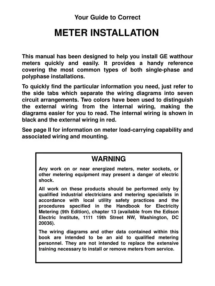
Your Guide to Correct METER INSTALLATION This manual has been designed to help you install GE watthour meters quickly and easily. It provides a handy reference covering the most common types of both single-phase and polyphase installations.

E N D
Your Guide to Correct METER INSTALLATION This manual has been designed to help you install GE watthour meters quickly and easily. It provides a handy reference covering the most common types of both single-phase and polyphase installations. To quickly find the particular information you need, just refer to the side tabs which separate the wiring diagrams into seven circuit arrangements. Two colors have been used to distinguish the external wiring from the internal wiring, making the diagrams easier for you to read. The internal wiring is shown in black and the external wiring in red. See page II for information on meter load-carrying capability and associated wiring and mounting. WARNING Any work on or near energized meters, meter sockets, or other metering equipment may present a danger of electric shock. All work on these products should be performed only by qualified industrial electricians and metering specialists in accordance with local utility safety practices and the procedures specified in the Handbook for Electricity Metering (9th Edition), chapter 13 (available from the Edison Electric Institute, 1111 19th Street NW, Washington, DC 20036). The wiring diagrams and other data contained within this book are intended to be an aid to qualified metering personnel. They are not intended to replace the extensive training necessary to install or remove meters from service.
WHERE TO FIND IT 1 Single-phase, 2-wire circuits Single-phase, 3-wire circuits Network, 3-wire and 3-phase, 3-wire circuits Three-phase, 3-wire circuits Three-phase, wye, 4-wire circuits Three-phase, delta, 4-wire circuits Miscellaneous circuits 1 2 3 4 5 6 7
METER CLASSES Modem-type meters in socket and bottom-connected construction are designated as Class 100, Class 200 or Class 10 or 20. Class 100 meters (15-ampere test rating) are rated 15 amperes but are capable of carrying, and measuring accurately, loads up to 100 amperes when suitably wired and mounted. Class 200 meters (30-ampere test rating) similarly have extended load capacity up to 200 amperes when suitably wired and mounted. Class 10 or 20 (transformer rated) meters are used with current transformers and require special sockets with circuit-closing devices. For complete details on single-phase and polyphase meters, current and voltage transformers, and all socket mountings. contact the GE Meter Business Department, Somersworth, NH 03878. METER MULTIPLIERS Transformer Factor (‘TF”)—The proper multiplier for Transformer rated meters with secondary reading registers must always include the ‘TF,” i.e.. CT ratio, or CT ratio x VT ratio when VT’s are used. NOTE: Primary-reading registers have transformer ratings on nameplate and multipliers of 1, 10, 100, or 1000. II
METERING SYMBOLS Kh = Watthour constant (or test constant) is the watthours per revolution of the meter disk PKh = Primary watthour constant (watthours per revolution of the disk, primary rating) = Test constant X TF Rr = Register ratio (turns of register worm gear for one revolution of fastest dial {right hand} pointer) Rs = Shaft gear reduction (ratio between rotor shaft and engaging gear) NOTE: Rs formerly designated as Gr Rg = Gear ratio (number of revolutions of the disk for one revolution of fastest dial {right hand} pointer) TF = Transformer factor = CTR x VTR Kr = Register multiplier (or dial constant). Multiply dial reading by Kr for kilowatt-hours
Kh (watthour constant) = PKhKhXTF = KhXCTR X VTR Kr (Dial Constant) = Rg (Gear ratio) = RrX Rs Rg (for GE Meters, except V-60, DS-50 and DS-60 family meters) = RrX 100 Rg (for V-60, DS-50 and DS-60 family meters) = RrX 50 Rr (register ratio) = Watts = 10,000 X Kr Rr XRs KhX RrX RhX TF 10,000 10,000 X Kr TF X KhX Rs 3,600 X disk rev X PKh T (time in seconds for disk rev) METERING FORMULAE
PKhX rev of disk 1,000 PKhX rev of disk 1,000 WATTHOUR-METER CONSTANTS AND REGISTER DATA The watthours per revolution of the meter disk is called the watthour constant (Kh). When watthour meters are used with instrument transformers (transformer-rated), the secondary watthours per revolution of the disk is the test constant (Kh); the product of the test constant, the current-transformer (CT) ratio, and the voltage-transformer (VT) ratio is the primary meter constant (PKh). The gear ratio (Rg) is the gear-train ratio between the rotor shaft and the fastest pointer shaft. It is the register-ratio (Rr) multiplied by the gear reduction (Rs) between the rotor shaft and the shaft of the worm gear or the gear meshing with it. The gear reduction at the shaft (Rs) is 100 for all GE meters except the V-60, DS-50 and DS-60 family meters. In the V-60, DS-50 and DS-60 meters Rs is 50. The register multiplier (Kr) is the constant by which the dial reading must be multiplied to obtain kilowatt-hours. For most self-contained meters, this is 1. There is a definite relation between these quantities. The watthours measured over a given period are, of course, PKh X revolutions of the disk. Therefore, the kilowatt-hours = The kilowatt-hours also equal revolutions of the fastest (first) pointer X 10 X Kr = new first pointerX10XKr
10,000 Kr PKh 10,000Kr RsX PKh 100Kr PKh 200Kr PKh rev of disk Rev of 1st pointer 10 X KrX 1,000 PKh Rg Rs WATTHOUR-METER CONSTANTS AND REGISTER DATA (cont) Gear ratio Rg = = = Register Ratio Rr = = For all GE meters except V-60, DS-50 and DS-60 series meters: R = For V-60, DS-50 and DS-60 series meters: R =
khX r Kh XR khX r Kh XR Ri R TEST FORMULAE Portable Watthour Meter Standard A = X100 (with no corrections for portable standard) A = X100 X Astd (over-all meter accuracy) where: A = percent accuracy of meter and Astd = percent accuracy of standard Kh= watthour constant of meter under test r = revolutions of meter under test Kh = watthour constant of standard R = revolutions of portable standard Ri = Where: Ri = calculated revolutions of standard A = X 100 percent accuracy khX r Kh
1 3 • TEST FORMULAE (cont) • Rules for Determining Calibrating Constants • When testing polyphase watthour meters with a single-phase portable watthour meter standard, the value of one revolution of the disk of the meter under test varies with the connections. Thus, a test constant, called a calibration constant (Calib C), is used which relates to the watthour meter constant kh as follows: • 1. Testing Two-stator Meters • 3-wire 3 phase / 3 or 4-wire 2-phase • Individual circuits Calib C = kh • Circuits in series Calib C = ½ kh • 4-wire Y 3 phase (2 ½ stator) • Individual circuits: • Single Coil Calib C = kh • Double Coil Calib C = ½ kh • Three Circuits in series Calib C = ¼ kh • 4-wire Delta (), 3 Phase • Individual circuits: • 2-wire Coil Calib C = kh • 3-wire coil windings • Separately Calib C = 2xkh • In Series Calib C = kh • Three Circuits in series Calib C = ½ kh • 2. Testing Three-stator Meter • 4 wire Y 3 phase • Individual Stators Calib C = kh • Two stators in series Calib C = ½ X kh • Three stators in series Calib C = X kh • 4-wire Delta (), 3 Phase • Individual stators Calib C = kh • Two 120-V stators in series Calib C = ½ X kh
1 3 khX r X 3,600 X 11 percent w X t TEST FORMULAE (cont) Rules for Determining Calibrating Constants 3. Totalizing 3-wire 3 phase / 2 wire single-phase Individual circuits Calib C = kh Two 240-V stators in series Calib C = ½ X kh 3-wire 3 phase / 3-wire single-phase Individual circuits: Individual Stators Calib C = kh Two stators in series Calib C = ½ kh Three stators in series Calib C = kh Instrument Test Method A = Where A = Percent accuracy kh = watthour meter constant in watthours per revolution of the disk r= revolutions of meter under test 3600= number of seconds in an hour w= watts load (with corrections for instrument inaccuracy). Also, w= voltage X amperes X number of stators, when tested on single- phase. Also, w= voltage X amperes X circuit constant (ie: 3 for 3-wire, 3- phase, when tested on polyphase t = time of test (seconds)
watts X t 3600 Determination of Watts Load The watthours measured by watthour meter are: PKh X rev of disk = or as usually written