Download
1 / 14
150 likes | 184 Views
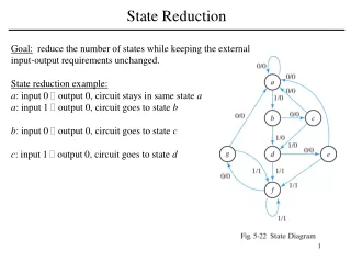
State Reduction. Goal: reduce the number of states while keeping the external input-output requirements unchanged. State reduction example: a : input 0 output 0, circuit stays in same state a a : input 1 output 0, circuit goes to state b

E N D
State Reduction Goal: reduce the number of states while keeping the external input-output requirements unchanged. State reduction example: a: input 0 output 0, circuit stays in same state a a:input 1 output 0, circuit goes to state b b: input 0 output 0, circuit goes to state c c: input 1 output 0, circuit goes to state d
State Reduction Present StateNext StateOutput x = 0 x = 1 x = 0 x = 1 a a b 0 0 b c d 0 0 c a d 0 0 d e f 0 1 e a f 0 1 f g f 0 1 g a f 0 1
State Reduction State Reduction Algorithm: Two states are equivalent if, for each member of the set inputs, they give the same output and send the circuit to the same state or equivalent state. Present StateNext StateOutput x = 0 x = 1 x = 0 x = 1 a a b 0 0 b c d 0 0 c a d 0 0 d e f 0 1 e a f 0 1 f g f 0 1 g a f 0 1 e equivalent states row with present state g is removed, and state g is replaced by state e each time it occurs.
State Reduction State Reduction Algorithm: Two states are equivalent if, for each member of the set inputs, they give the same output and send the circuit to the same state or equivalent state. Present StateNext StateOutput x = 0 x = 1 x = 0 x = 1 a a b 0 0 b c d 0 0 c a d 0 0 d e f 0 1 e a f 0 1 f e f 0 1 d d equivalent states row with present state f is removed, and state f is replaced by state d each time it occurs.
State Reduction Present StateNext StateOutput x = 0 x = 1 x = 0 x = 1 a a b 0 0 b c d 0 0 c a d 0 0 d e d 0 1 e a d 0 1
State Coded Binary Assignment Present StateNext StateOutput x = 0 x = 1 x = 0 x = 1 a 000 a 000 b 001 0 0 b 001 c 010 d 0110 0 c 010 a 000 d 011 0 0 d 011 e 100 d 011 0 1 e 100 a 000 d 011 0 1 Reduced State Table with Binary Assignment
Sequential Circuits: Design Procedure • Recommended Design Steps • Derive the state diagram from the word description and the • specifications of the desired operation. • Reduce the number of states if necessary. • Assign binary values to the states. • Obtain the binary coded-state table. • Chose the type of flip-flops to be used. • Derive the simplified flip-flop input and output equations. • Draw the logic diagram.
Sequence Detector Sequential Circuit Design a circuit that detects three or more consecutive 1’s in a string of bits using D Flip-Flops. • Start with state S0 • If the input is 0 circuit stays in the same state • If the next input is 1 circuit goes to S1 to indicate that 1 was detected • If the next input is 1 circuit goes to S2 to indicate that the arrival of two • consecutive 1’s. • But if the input were 0 circuit goes back to S0. • The third consecutive 1 sends the circuit to S3. • If more 1 are detected circuit stays in S3. • Draw the state diagram.
Sequence Detector Sequential Circuit • State table is derived directly from the state diagram. • We choose 2 D Flip-Flops (outputs A, B) • There is one input x and one output y D flip-flop state Equations: Present State Next State Input Output • This state table is the result • of Moore implementation: • output depends on the present state only. We can, however, implement a Mealy machine: • output depends on the present state and the input.
Sequence Detector Sequential Circuit • Obtain the simplified functions from the K-Maps:
Design using JK Flip-Flops In order to determine the input equations for the JK flip-flops, it is necessary to derive a functional relationship between the state table and the input equations. Present State Next State Input Flip-Flop inputs Flip-Flop Excitation table: