Download
1 / 23
230 likes | 314 Views
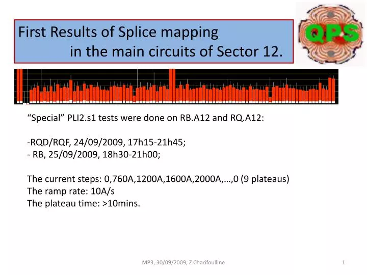
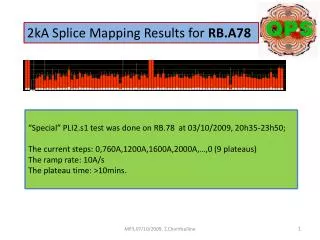
First Results of Splice mapping in the main circuits of Sector 12. “Special” PLI2.s1 tests were done on RB.A12 and RQ.A12: RQD/RQF, 24/09/2009, 17h15-21h45; RB, 25/09/2009, 18h30-21h00; The current steps: 0,760A,1200A,1600A,2000A,…,0 (9 plateaus) The ramp rate: 10A/s

E N D
First Results of Splice mapping in the main circuits of Sector 12. • “Special” PLI2.s1 tests were done on RB.A12 and RQ.A12: • RQD/RQF, 24/09/2009, 17h15-21h45; • RB, 25/09/2009, 18h30-21h00; • The current steps: 0,760A,1200A,1600A,2000A,…,0 (9 plateaus) • The ramp rate: 10A/s • The plateau time: >10mins. MP3, 30/09/2009, Z.Charifoulline
nQPS layout for bus-bar protection – example (R.Denz, MP3, 19/08/2009) “U_MAG” – magnet signal, which is total voltage drop on the “reference” magnet; “U_RES = Ubus–α*U_MAG” - bus bar signal; α=93.0E-5 (dipoles) and α=51.0E-3 (quads) – defaults values for dI/dt compensation; • _SPLICE signals are sent directly to analysis tools via special subscription to QPS supervision signals (developing by Odd Andreassen, additional few weeks?) • All signals are transferred to QPS supervision and TIMBER, certain status flags as well to LASER • All signals are recorded on change; dead-bands apply only to LSB • LSB U_RES = 1.5 nV(24bit, ±12.5mV) • LSB U_MAG = 305 nV MP3, 30/09/2009, Z.Charifoulline
nQPS layout for bus-bar protection – example (R.Denz, MP3, 19/08/2009) “U_MAG” – magnet signal, which is total voltage drop on the “reference” magnet; “U_RES = Ubus–α*U_MAG” - bus bar signal; α=93.0E-5 (dipoles) and α=51.0E-3 (quads) – defaults values for dI/dt compensation; • _SPLICE signals are sent directly to analysis tools via special subscription to QPS supervision signals (developing by Odd Andreassen, additional few weeks?) • All signals are transferred to QPS supervision and TIMBER, certain status flags as well to LASER • All signals are recorded on change; dead-bands apply only to LSB • LSB U_RES = 1.5 nV(24bit, ±12.5mV) • LSB U_MAG = 305 nV U_RES_SPLICE(I) = U0 + Rbus*I + {∆α*U_MAG_SPLICE(I)}; U_MAG_SPLICE(I) = U0 + Rmag*I; MP3, 30/09/2009, Z.Charifoulline
A12.RQD/RQF: U_RES_SPLICE vs Time & I_MEAS vs Time MP3, 30/09/2009, Z.Charifoulline
A12.RQD/RQF: U_RES_SPLICE vs Time & I_MEAS vs Time MP3, 30/09/2009, Z.Charifoulline
A12.RQD/RQF: U_RES_SPLICE vs I_MEAS MP3, 30/09/2009, Z.Charifoulline
A12.RQD/RQF: BusSegmentReistancevsnQPS Crate MP3, 30/09/2009, Z.Charifoulline
A12.RQD/RQF: BusSegmentReistancevsnQPS Crate MP3, 30/09/2009, Z.Charifoulline
A12.RQD/RQF: BusSegmentReistancevsnQPS Crate MP3, 30/09/2009, Z.Charifoulline
A12.RQD/RQF: BusSegmentReistancevsnQPS Crate MP3, 30/09/2009, Z.Charifoulline
A12.RQD/RQF: BusSegmentReistancevsnQPS Crate MP3, 30/09/2009, Z.Charifoulline
A12.RQD/RQF: BusSegmentReistancevsnQPS Crate MP3, 30/09/2009, Z.Charifoulline
A12.RQD/RQF: BusSegmentReistancevsnQPS Crate 8 32 18 8 14 Thanks to C.Lorin, F.Bertinelli for Splice Num Mapping MP3, 30/09/2009, Z.Charifoulline
A12.RQD/RQF: BusSegmentReistancevsnQPS Crate 8 32 18 8 14 Thanks to C.Lorin, F.Bertinelli for Splice Num Mapping MP3, 30/09/2009, Z.Charifoulline
A12.RB: BusSegmentReistancevsnQPS Crate (current flow) MP3, 30/09/2009, Z.Charifoulline
A12.RB: BusSegmentReistancevsnQPS Crate (current flow) Thanks to C.Lorin, F.Bertinelli for Splice Num Mapping MP3, 30/09/2009, Z.Charifoulline
A12.RB: BusSegmentReistancevsnQPS Crate (current flow) Thanks to C.Lorin, F.Bertinelli for Splice Num Mapping MP3, 30/09/2009, Z.Charifoulline
32 splices MP3, 30/09/2009, Z.Charifoulline
Sector A12, nQPS, Preliminary conclusion (29/09/2009): • bus segments resistance measurement based on U_RES signals looks very promising; • inductance compensation works well and almost done, there are few units to be fixed; • next step will be to perform nQPS-IST and switch on the protection, I think; • but, magnets resistance measurements based on U_MAG signals are noisy and not yet fully • analyzed to be interpreted correctly; MP3, 30/09/2009, Z.Charifoulline
A12.RB: Snapshots MP3, 30/09/2009, Z.Charifoulline
A12.RB: Snapshots MP3, 30/09/2009, Z.Charifoulline
A12.RQD/F: Snapshots MP3, 30/09/2009, Z.Charifoulline
A12.RQD/F: Snapshots MP3, 30/09/2009, Z.Charifoulline


![High-Throughput Analysis of Genomic Data [S7] E NRIQUE B LANCO](https://cdn2.slideserve.com/3859222/high-throughput-analysis-of-genomic-data-s7-e-nrique-b-lanco-dt.jpg)