Download
1 / 19
200 likes | 309 Views
Active Target Multistatic Receiver (ATMR). John Paden. Project Background. KU’s Center for Remote Sensing of Ice Sheets was awarded an NSF MRI grant to build a new 24-channel 150-600 MHz radar system

E N D
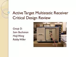
Active Target Multistatic Receiver(ATMR) John Paden
Project Background • KU’s Center for Remote Sensing of Ice Sheets was awarded an NSF MRI grant to build a new 24-channel 150-600 MHz radar system • Part of the award includes funds to build a calibration system for the new radar. This calibration system is called the “Active Target Multistatic Receiver” or ATMR • The proposed EECS 502 project is to build a complete ATMR system.
Sea Level Rise Images from http://www.nsidc.org/
Ice Core Site Selection Image from http://www.nsidc.org/
Large Array • 24-channel system composed of three 8-element subarrays • Explore MIMO radar concept • Improved swath imaging
Wide Bandwidth • Wide bandwidth to resolve fine layering from the ice surface to the ice bottom.
ATMR Motivation • Monitor system health precisely • Array calibration of 24 element VHF-UHF array difficult to impossible any other way • Channel equalization more critical because of wide bandwidth (4:1) • Active target allows radiometric calibration of radar AND processing system
System Operation Fig. 1. Illustration of radar transmission (Tx) and reception (Rx) in normal operation mode. Fig. 2. Illustration of radar transmission and reception in calibration mode. The radar’s transmission is (Tx) which is captured by the ATMR and the radar receives both the scattered signal (Rx) and the ATMR’s calibration signal (Cal).
System Description • Antenna • Use a single radar system antenna element • Calibration in anechoic chamber
System Description • RF Section • Create link budget for signal capture and injection • RF system block diagram and design reviews • Specify, order and test RF components • Assemble and test RF system
System Description • Digital Section • HDL to build DSP • Signal processing design • Develop modules and test benches • Integrate modules and complete lab test
System Description • Clock Synthesizer • Build AWG and DAQ clock synthesizers integrated to a GPS-synced oscillator. • Provide 1 PPS and position information to digital section with GPS receiver.
Final Integration • Integrate RF and Digital systems • Lab tests • Radar tests
Project Objectives • Test with radar system and verify that captured signal and injected signal measure system impulse response at expected power levels • Handle full 150 to 600 MHz bandwidth through pipelining and parallelization
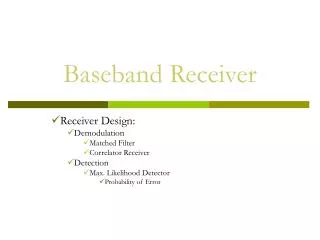
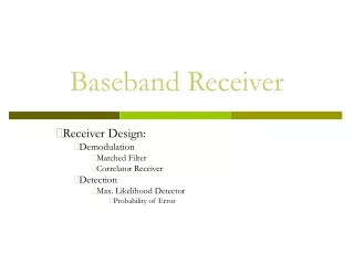
Skillsets • Antenna calibration • Radio system (transmit/receiver) design • RF component selection/testing • Digital signal processing: modulation, filtering, detection • HDL • Lab equipment (setup and programming)