Download
1 / 1
10 likes | 126 Views
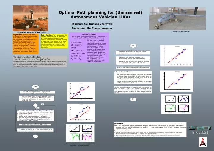
Start. Define the starting position and target position Define the Obstacle positions and shapes. Define the default path as a straight line connecting the starting point and target point. Define the state variables and the control variables as a single array in the default path definition.

E N D
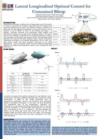
Start • Define the starting position and target position • Define the Obstacle positions and shapes • Define the default path as a straight line connecting the starting point and target point. • Define the state variables and the control variables as a single array in the default path definition Define the cost function calculation as objective function • Define the Constraint function • Use the models state equations and assign the values to consecutive state variables and control variables using the step wise linear integration. Define these equations as equality constraints for iterative calculations. • Define the equations of obstacle avoidance as inequality constraints for iterative calculations Start Call the fmincon function by using the cost function as the objective function, taking the constraint function as the nonlinear constraint function and using the limitations of the state variables, control variables as upper bounds and lower bounds. • Define the starting position and target position • Define the Obstacle positions and shapes • Define a control matrix with some predicted control values which are the factors of the maximum limits of the control variables and the total number of way points to N, i=0; END No i < N Yes • Call a weights assigned function repeatedly for each row vector of the control matrix and calculates weights for each vector. • In weights assign function • Using the control vector of corresponding index value the position vector of subsequent point is calculated • Using the position vector obstacle collisions will check, if they occurred a very big value assigned to weight else the value between 0 to 1 is assigned • Get the index of the minimum of the values • Calculate the position vector with corresponding control vector increment i. Stop Optimal Path planning for (Unmanned)Autonomous Vehicles, UAVs Student: Anil Krishna Veeravalli Supervisor: Dr. Plamen Angelov Unmanned Aerial vehicle Mars –Rover Unmanned Ground Vehicle Objective:The main aim of the project is to find out the optimal path or trajectory including their corresponding control parameters to control the vehicle dynamics in obstacle full dynamic environment. The vehicle should navigate in the obstacle full environment and reach the target point by avoiding the obstacles with minimizing the cost function defined in the aspect of minimising the changes in the control function. Introduction:From last decade, the demand of the concepts in the design and implementation of unmanned vehicles is increasing. The Path planning is one of the main concept in this area. The optimal control methodology and heuristic approach are used for path planning and the results obtained are compared. The state vector [x1 x2 x3 x4] represents the position parameters of the aircraft and the control vector [u1 u2] represents the controls that are using to move the aircraft. In the state vector x1 and x2 represents the North and East coordinates of the aircraft and x3 is the speed of the aircraft and x4 is the target point heading angle to the aircraft. In the control vector u1 and u2 represents the commanded acceleration and bank angle of the aircraft. The objective function (cost function): In this equation w1 and w2 represents the weights given to both values for calculating the cost function. The x1end, x2end represents the North and east coordinates of the end point of the path, xnt, xet represents the north and east coordinates of the target and t0, tf represents the starting and ending time of the path travel. Problem Definition: A simple model of the position kinematics of a single aircraft is taken for problem definition. The model is described as Start Conclusion: The DCNLP algorithm is proved to be one of the good procedures in path planning of unmanned vehicles but with the real time environment situation the computational complexity increases though it is better algorithm than heuristic approach. References: 1) Jayesh N. Aminy, Jovan D. Boskovi´cz, and Raman K. Mehra,’ A Fast and Efficient Approach to Path Planning for Unmanned Vehicles’, AIAA Guidance, Navigation, and Control Conference and Exhibit, 21 - 24 August2006, Keystone, Colorado. 2) Brian R. Geiger, Joseph F. Horn, Anthony M. DeLullo, and Lyle N. Long,’ Optimal Path Planning of UAVs Using Direct Collocation with Nonlinear Programming’, American Institute of Aeronautics and Astronautics conference, Aug., 2006. Fig. The bounded parameter constraint variation in UAV navigation – Heuristic Approach Student: Anil Krishna Veeravalli, First Supervisor: Dr. Plamen Angelov, Second Supervisor: Dr. Costas Xydeas