Download
1 / 46
460 likes | 493 Views
Learn how DHCP allows hosts to obtain IP addresses dynamically, supporting mobile users and efficient address reuse. Detailed overview and scenarios included. Networking Layer Slides Adapted with Key Concepts

E N D
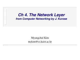
Networking Layer Slides originally prepared by Jim Kurose and Keith Ross (for their textbook Computer Networking: A Top Down Approach 4th edition) Adapted by Suman Banerjee for CS 640 Network Layer
DHCP: Dynamic Host Configuration Protocol Goal: allow host to dynamically obtain its IP address from network server when it joins network Can renew its lease on address in use Allows reuse of addresses (only hold address while connected an “on”) Support for mobile users who want to join network (more shortly) DHCP overview: • host broadcasts “DHCP discover” msg • DHCP server responds with “DHCP offer” msg • host requests IP address: “DHCP request” msg • DHCP server sends address: “DHCP ack” msg Network Layer
E B A DHCP client-server scenario 223.1.2.1 DHCP 223.1.1.1 server 223.1.1.2 223.1.2.9 223.1.1.4 223.1.2.2 arriving DHCP client needs address in this network 223.1.1.3 223.1.3.27 223.1.3.2 223.1.3.1 Network Layer
DHCP discover src : 0.0.0.0, 68 dest.: 255.255.255.255,67 yiaddr: 0.0.0.0 transaction ID: 654 DHCP client-server scenario arriving client DHCP server: 223.1.2.5 DHCP offer src: 223.1.2.5, 67 dest: 255.255.255.255, 68 yiaddrr: 223.1.2.4 transaction ID: 654 Lifetime: 3600 secs DHCP request src: 0.0.0.0, 68 dest:: 255.255.255.255, 67 yiaddrr: 223.1.2.4 transaction ID: 655 Lifetime: 3600 secs time DHCP ACK src: 223.1.2.5, 67 dest: 255.255.255.255, 68 yiaddrr: 223.1.2.4 transaction ID: 655 Lifetime: 3600 secs Network Layer
More on DHCP • Servers often have 2 sets of IP address • Static pool (to configure say, desktop machines) and dynamic pool (to configure transient machines) • Servers often use the policy of “ping-before-offer” for IP address allocation • If a (rogue) machine responds to a ping for an IP address in the dynamic pool, that IP address gets abandoned by the server Network Layer
IP addresses: how to get one? Q: How does network get subnet part of IP addr? A: gets allocated portion of its provider ISP’s address space ISP's block 11001000 00010111 00010000 00000000 200.23.16.0/20 Organization 0 11001000 00010111 00010000 00000000 200.23.16.0/23 Organization 1 11001000 00010111 00010010 00000000 200.23.18.0/23 Organization 2 11001000 00010111 00010100 00000000 200.23.20.0/23 ... ….. …. …. Organization 7 11001000 00010111 00011110 00000000 200.23.30.0/23 Network Layer
200.23.16.0/23 200.23.18.0/23 200.23.30.0/23 200.23.20.0/23 . . . . . . Hierarchical addressing: route aggregation Hierarchical addressing allows efficient advertisement of routing information: Organization 0 Organization 1 “Send me anything with addresses beginning 200.23.16.0/20” Organization 2 Fly-By-Night-ISP Internet Organization 7 “Send me anything with addresses beginning 199.31.0.0/16” ISPs-R-Us Network Layer
200.23.16.0/23 200.23.18.0/23 200.23.30.0/23 200.23.20.0/23 . . . . . . Hierarchical addressing: more specific routes ISPs-R-Us has a more specific route to Organization 1 Organization 0 “Send me anything with addresses beginning 200.23.16.0/20” Organization 2 Fly-By-Night-ISP Internet Organization 7 “Send me anything with addresses beginning 199.31.0.0/16 or 200.23.18.0/23” ISPs-R-Us Organization 1 Network Layer
IP addressing: the last word... Q: How does an ISP get block of addresses? A: ICANN: Internet Corporation for Assigned Names and Numbers • allocates addresses • manages DNS • assigns domain names, resolves disputes Network Layer
NAT: Network Address Translation rest of Internet local network (e.g., home network) 10.0.0/24 10.0.0.1 10.0.0.4 10.0.0.2 138.76.29.7 10.0.0.3 Datagrams with source or destination in this network have 10.0.0/24 address for source, destination (as usual) All datagrams leaving local network have same single source NAT IP address: 138.76.29.7, different source port numbers Network Layer
NAT: Network Address Translation • Motivation: local network uses just one IP address as far as outside world is concerned: • range of addresses not needed from ISP: just one IP address for all devices • can change addresses of devices in local network without notifying outside world • can change ISP without changing addresses of devices in local network • devices inside local net not explicitly addressable, visible by outside world (a security plus). Network Layer
NAT: Network Address Translation Implementation: NAT router must: • outgoing datagrams:replace (source IP address, port #) of every outgoing datagram to (NAT IP address, new port #) . . . remote clients/servers will respond using (NAT IP address, new port #) as destination addr. • remember (in NAT translation table) every (source IP address, port #) to (NAT IP address, new port #) translation pair • incoming datagrams:replace (NAT IP address, new port #) in dest fields of every incoming datagram with corresponding (source IP address, port #) stored in NAT table Network Layer
2 4 1 3 S: 138.76.29.7, 5001 D: 128.119.40.186, 80 S: 10.0.0.1, 3345 D: 128.119.40.186, 80 1: host 10.0.0.1 sends datagram to 128.119.40.186, 80 2: NAT router changes datagram source addr from 10.0.0.1, 3345 to 138.76.29.7, 5001, updates table S: 128.119.40.186, 80 D: 10.0.0.1, 3345 S: 128.119.40.186, 80 D: 138.76.29.7, 5001 NAT: Network Address Translation NAT translation table WAN side addr LAN side addr 138.76.29.7, 5001 10.0.0.1, 3345 …… …… 10.0.0.1 10.0.0.4 10.0.0.2 138.76.29.7 10.0.0.3 4: NAT router changes datagram dest addr from 138.76.29.7, 5001 to 10.0.0.1, 3345 3: Reply arrives dest. address: 138.76.29.7, 5001 Network Layer
NAT: Network Address Translation • 16-bit port-number field: • 60,000 simultaneous connections with a single LAN-side address! • NAT is controversial: • routers should only process up to layer 3 • violates end-to-end argument • NAT possibility must be taken into account by app designers, eg, P2P applications • address shortage should instead be solved by IPv6 Network Layer
NAT traversal problem • client wants to connect to server with address 10.0.0.1 • server address 10.0.0.1 local to LAN (client can’t use it as destination addr) • only one externally visible NATted address: 138.76.29.7 • solution 1: statically configure NAT to forward incoming connection requests at given port to server • e.g., (123.76.29.7, port 2500) always forwarded to 10.0.0.1 port 25000 10.0.0.1 Client ? 10.0.0.4 138.76.29.7 NAT router Network Layer
NAT traversal problem • solution 2: Universal Plug and Play (UPnP) Internet Gateway Device (IGD) Protocol. Allows NATted host to: • learn public IP address (138.76.29.7) • add/remove port mappings (with lease times) i.e., automate static NAT port map configuration 10.0.0.1 IGD 10.0.0.4 138.76.29.7 NAT router Network Layer
10.0.0.1 NAT router NAT traversal problem • solution 3: relaying (used in Skype) • NATed client establishes connection to relay • External client connects to relay • relay bridges packets between to connections 2. connection to relay initiated by client 1. connection to relay initiated by NATted host 3. relaying established Client 138.76.29.7 Network Layer
IPv6 • Initial motivation:32-bit address space soon to be completely allocated. • Additional motivation: • header format helps speed processing/forwarding • header changes to facilitate QoS IPv6 datagram format: • fixed-length 40 byte header • no fragmentation allowed Network Layer
IPv6 Header (Cont) Priority: identify priority among datagrams in flow Flow Label: identify datagrams in same “flow.” (concept of“flow” not well defined). Next header: identify upper layer protocol for data Network Layer
Other Changes from IPv4 • Checksum:removed entirely to reduce processing time at each hop • Options: allowed, but outside of header, indicated by “Next Header” field • ICMPv6: new version of ICMP • additional message types, e.g. “Packet Too Big” • multicast group management functions Network Layer
Transition From IPv4 To IPv6 • Not all routers can be upgraded simultaneous • no “flag days” • How will the network operate with mixed IPv4 and IPv6 routers? • Tunneling: IPv6 carried as payload in IPv4 datagram among IPv4 routers Network Layer
F A B E F E B A tunnel Logical view: IPv6 IPv6 IPv6 IPv6 Physical view: IPv6 IPv6 IPv6 IPv6 IPv4 IPv4 Tunneling Network Layer
Flow: X Src: A Dest: F data Flow: X Src: A Dest: F data Flow: X Src: A Dest: F data Flow: X Src: A Dest: F data A B E F F A B E C D Src:B Dest: E Src:B Dest: E Tunneling tunnel Logical view: IPv6 IPv6 IPv6 IPv6 Physical view: IPv6 IPv6 IPv6 IPv6 IPv4 IPv4 A-to-B: IPv6 E-to-F: IPv6 B-to-C: IPv6 inside IPv4 B-to-C: IPv6 inside IPv4 Network Layer
IP Multicast Network Layer
duplicate creation/transmission duplicate duplicate in-network duplication sourceduplication R4 R2 R4 R2 R3 R3 R1 R1 Broadcast Routing • deliver packets from source to all other nodes • source duplication is inefficient: • source duplication: how does source determine recipient addresses? Network Layer
In-network duplication • flooding: when node receives brdcst pckt, sends copy to all neighbors • Problems: cycles & broadcast storm • controlled flooding: node only brdcsts pkt if it hasn’t brdcst same packet before • Node keeps track of pckt ids already brdcsted • Or reverse path forwarding (RPF): only forward pckt if it arrived on shortest path between node and source • spanning tree • No redundant packets received by any node Network Layer
(b) Broadcast initiated at D (a) Broadcast initiated at A A A D D G G B B E E F F c c Spanning Tree • First construct a spanning tree • Nodes forward copies only along spanning tree Network Layer
A A D D G G B E B E F F c c Spanning Tree: Creation • Center node • Each node sends unicast join message to center node • Message forwarded until it arrives at a node already belonging to spanning tree 3 4 2 5 1 • Stepwise construction of spanning tree (b) Constructed spanning tree Network Layer
Source-based trees Multicast Routing: Problem Statement • Goal: find a tree (or trees) connecting routers having local mcast group members • tree: not all paths between routers used • source-based: different tree from each sender to rcvrs • shared-tree: same tree used by all group members Shared tree
Approaches for building mcast trees Approaches: • source-based tree: one tree per source • shortest path trees • reverse path forwarding • group-shared tree: group uses one tree • minimal spanning (Steiner) • center-based trees …we first look at basic approaches, then specific protocols adopting these approaches
1 i 5 4 3 6 2 Shortest Path Tree • mcast forwarding tree: tree of shortest path routes from source to all receivers • Dijkstra’s algorithm S: source LEGEND R1 R4 router with attached group member R2 router with no attached group member R5 link used for forwarding, i indicates order link added by algorithm R3 R7 R6
Reverse Path Forwarding if (mcast datagram received on incoming link on shortest path back to center) then flood datagram onto all outgoing links else ignore datagram • rely on router’s knowledge of unicast shortest path from it to sender • each router has simple forwarding behavior:
Reverse Path Forwarding: example S: source LEGEND R1 R4 router with attached group member R2 router with no attached group member R5 datagram will be forwarded R3 R7 R6 datagram will not be forwarded • result is a source-specific reverse SPT • may be a bad choice with asymmetric links
Reverse Path Forwarding: pruning • forwarding tree contains subtrees with no mcast group members • no need to forward datagrams down subtree • “prune” msgs sent upstream by router with no downstream group members LEGEND S: source R1 router with attached group member R4 router with no attached group member R2 P P R5 prune message links with multicast forwarding P R3 R7 R6
Shared-Tree: Steiner Tree • Steiner Tree: minimum cost tree connecting all routers with attached group members • problem is NP-complete • excellent heuristics exists • not used in practice: • computational complexity • information about entire network needed • monolithic: rerun whenever a router needs to join/leave
Center-based trees • single delivery tree shared by all • one router identified as “center” of tree • to join: • edge router sends unicast join-msg addressed to center router • join-msg “processed” by intermediate routers and forwarded towards center • join-msg either hits existing tree branch for this center, or arrives at center • path taken by join-msg becomes new branch of tree for this router
Center-based trees: an example Suppose R6 chosen as center: LEGEND R1 router with attached group member R4 3 router with no attached group member R2 2 1 R5 path order in which join messages generated R3 1 R7 R6
Internet Multicasting Routing: DVMRP • DVMRP: distance vector multicast routing protocol, RFC1075 • flood and prune: reverse path forwarding, source-based tree • RPF tree based on DVMRP’s own routing tables constructed by communicating DVMRP routers • no assumptions about underlying unicast • initial datagram to mcast group flooded everywhere via RPF • routers not wanting group: send upstream prune msgs
DVMRP: continued… • soft state: DVMRP router periodically (1 min.) “forgets” branches are pruned: • mcast data again flows down unpruned branch • downstream router: reprune or else continue to receive data • routers can quickly regraft to tree • following IGMP join at leaf • odds and ends • commonly implemented in commercial routers • Mbone routing done using DVMRP
Tunneling Q: How to connect “islands” of multicast routers in a “sea” of unicast routers? logical topology physical topology • mcast datagram encapsulated inside “normal” (non-multicast-addressed) datagram • normal IP datagram sent thru “tunnel” via regular IP unicast to receiving mcast router • receiving mcast router unencapsulates to get mcast datagram
not dependent on any specific underlying unicast routing algorithm (works with all) two different multicast distribution scenarios : PIM: Protocol Independent Multicast • Dense: • group members densely packed, in “close” proximity. • bandwidth more plentiful • Sparse: • # networks with group members small wrt # interconnected networks • group members “widely dispersed” • bandwidth not plentiful
Dense group membership by routers assumed until routers explicitly prune data-driven construction on mcast tree (e.g., RPF) bandwidth and non-group-router processing profligate Sparse: no membership until routers explicitly join receiver- driven construction of mcast tree (e.g., center-based) bandwidth and non-group-router processing conservative Consequences of Sparse-Dense Dichotomy:
PIM- Dense Mode • flood-and-prune RPF, similar to DVMRP but • underlying unicast protocol provides RPF info for incoming datagram • less complicated (less efficient) downstream flood than DVMRP reduces reliance on underlying routing algorithm • has protocol mechanism for router to detect it is a leaf-node router
center-based approach router sends join msg to rendezvous point (RP) intermediate routers update state and forward join after joining via RP, router can switch to source-specific tree increased performance: less concentration, shorter paths PIM - Sparse Mode R1 R4 join R2 join R5 join R3 R7 R6 all data multicast from rendezvous point rendezvous point
sender(s): unicast data to RP, which distributes down RP-rooted tree RP can extend mcast tree upstream to source RP can send stop msg if no attached receivers “no one is listening!” PIM - Sparse Mode R1 R4 join R2 join R5 join R3 R7 R6 all data multicast from rendezvous point rendezvous point
4. 1 Introduction 4.2 Virtual circuit and datagram networks 4.3 What’s inside a router 4.4 IP: Internet Protocol Datagram format IPv4 addressing ICMP IPv6 4.5 Routing algorithms Link state Distance Vector Hierarchical routing 4.6 Routing in the Internet RIP OSPF BGP 4.7 Broadcast and multicast routing Chapter 4: summary Network Layer