Download
1 / 20
200 likes | 381 Views
ALICE : Superconductive Energy Recovery Linac (ERL) “Quick course” for new machine operators Part 1: Machine description and basic ERL physics . Y. Saveliev November 2013. Structure : Part 1 : Machine description and basic ERL physics

E N D
ALICE : Superconductive Energy Recovery Linac (ERL) “Quick course” for new machine operators Part 1: Machine description and basic ERL physics Y. Saveliev November 2013
Structure : Part 1 : Machine description and basic ERL physics Part 2 : Machine components and systems in more detail Part 3 : Experimental and Operational Procedures Aim : To give some background information and some basic knowledge of ALICE for new machine operators Final goal: To “train” new operators for independent (or semi-independent) start-up and operation of ALICE - needs actual shift work alongside experienced members of ALICE commissioning team; - needs a certain amount of time invested into learning various things re. ALICE Sources of information: ALICE Wiki pages : http://projects.astec.ac.uk/ERLPManual/index.php/Main_Page
The ALICE Facility @ Daresbury Laboratory Accelerators and Lasers InCombined Experiments An accelerator R&D facility based on a superconducting energy recovery linac photoinjector laser Free Electron Laser EMMA superconducting linac DC gun superconducting booster
The ALICE (ERLP) Facility @ Daresbury Laboratory Tower or lab picture Accelerators and Lasers In Combined Experiments
Some notes to remember … • ALICE was originally built as ERLP : “cheap & cheerful” • - many systems /subsystems are not ideal • ALICE is a “moody” machine • - machine behaviour changes from time to time • ALICE is not a “turn key” machine • - needs time and experienced operators to start it up and achieve what is needed (i.e. energy recovery, FEL operation, THz generation) • - some measures are underway to improve things • ALICE is not particularly stable machine ( … “cheap & cheerful” !) • - cannot just apply settings from yesterday to get the same beam characteristics today • - some important machine parameters tend to drift during the day (most notably – RF phases) • - some measures are underway to improve things • Longitudinal beam dynamics is of primary importance • - make it even slightly wrong – FEL/THz will not work ! ALICE cannot be operated by just following step-by-step instructions and pushing right buttons at the right time the operator needs to know basics of machine physics and operational features
ALICE schematic and main components Photoinjector laser (28ps) Photogun (325keV) RF buncher (1.3GHz) RF SC booster (1.3GHz; 6.5MeV) Injector beamline main linac (1.3GHz; 26.0MeV) 1st arc Compression chicane (<1ps bunches) THz source undulator (IR FEL) 2nd arc Main linac (energy recovery; 26.0MeV 6.5MeV) main beam dump Systems : cryogenic , vacuum, magnetic , RF, diagnostics, controls …
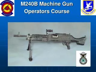
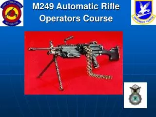
HV DC Photogun Superconductive linac
Train repetition frequency : 1-10Hz 0.1 – 1.0s Timing structure 0.01- 100us Train of bunches (variable length) Variable distance between bunches IR-FEL : 16.26MHz (62ns) THz : 40.63MHz (25ns) Bunch length (compressed) : ~ 0.001ns
Transverse beam manipulation Dipoles : turn the beam around the machine - also have vertical (V) and horizontal (H) properties focussing properties depending on poles geometry Solenoids : focus beam azimuthally symmetrically (but also rotate the beam by ~ 45deg in ALICE case) Quadrupoles : focus beam in one plane AND defocus it in the other plane F quads (green) : focus in H plane D quads (red) : defocus in H plane Correctors (H&V) : relatively weak dipoles to correct beam steering Sextupoles : for second order longitudinal phase space correction but can also act as quads if the beam is not centered RF fields : also have focussing and steering properties
Beam diagnostics Screens : YAGs in injector and mostly OTRs (Optical Transition Radiation) in the rest of the machine BPMs (Beam Position Monitors) : measure the position of the beam centroid (wrt the BPM reference that may not necessarily be the centre of the beamline ! ) Slits : narrow ~100um slits to cut out a slice of the beam (mainly for emittance measurements) Energy spectrometers : measure mean beam energy and energy spread; can be also used for bunch length measurements Faraday cups : measure beam current and hence bunch charge TOA (Time-Of-Arrival) monitors : BPMs are used as TOA monitors ; main tool for the buncher RF phasing Other diagnostics : specific for machine and radiation characterisation …
Why do we need short bunches ? • FEL gain (and therefore the FEL start-up) depends on peak current • THz power depends GREATLY on bunch length • - coherent enhancement when the bunch length is shorter than THz wavelength ; • - coherent THz are may orders of magnitude more intense; • - 1ps 1THz THz spectrum FEL gain v bunch length and energy spread
Longitudinal phase space evolution E E E z z z After booster : Positive energy chirp again due to complex physics during acceleration; Can be made zero chirp with some “unusual” booster settings NOTE: booster compresses the bunch even further! After DC gun : Positive energy chirp due to space charge; Velocity de-bunching (325keV ! Non-relativistic !) After buncher : Negative energy chirp Imprinted velocity bunching takes place
Longitudinal phase space evolution E E E z z z After main linac: Linac RF phase chosen to imprint negative chirp again; After magnetic chicane : Bunch is fully compressed for THz generation & FEL operation After 2nd ARC : Bunch is de-compressed for energy recovery (special ARC2 settings)
Longitudinal phase space manipulation • Negative linear energy chirp after the linac (dE/dz) MUST be of specific value to match the bunch compressing properties of the magnetic compressor (R56 ~ 28cm) • - if not, the bunch will be undercompressed or overcompressed longer bunch in any case • Second order effects (curvature of the longitudinal phase space) can be controlled by sextupoles in the Arcs … • - but this is very much still a “black magic” • AR1 is to be set achromatic and isochronous (R56=0) but it is not easy to achieve (and measure!) • - many factors affect R56 of the ARC1 … even steering ! … e.g. sextupoles start to behave as quadrupoles when the beam is not centered • Even the transverse properties of the accelerator lattice affect the bunch shortness • Some tweaking is nearly always needed to achieve the required bunch shortness THz THz Bunch is fully compressed longitudinally but “skewed” wrt the beam trajectory effective bunch lengthening
Beam loading SC cavities store large (but not infinite !) amount of RF energy Bunch train arrival eats up stored RF energy that has to be replenished from the RF source “Phase pulling” : phase of the accelerating RF field is also varying under beam loading Both factor have to be controlled by the LLRF system but it is not instantaneous hence there is a limitation on average current to accelerate (and bunch charge) that keeps beam loading effects at acceptable level ( bunch charge is 60pC currently at 16 or 41MHz ) Beam loading applies also to NC cavities ( = buncher on ALICE) Digital LLRF system with feed-forward capability should alleviate beam loading problems (still not fully implemented on ALICE) Q(loaded)~106 tf ~ 0.3ms Buncher and booster are most affected by beam loading (they are not in energy recovery mode !) Main Linac is least affected if ER is perfect (except some transients)
THz Radiation from ALICE Alice 60 pC deliver 14 nJ /pulse into 4 mm FWHM in diagnostics room Beamline transmission = 20% (overfilling M3) Source 70 nJ/pulse Overfilling mirror M3 limits transport efficiency
ALICE IR FEL • period 27mm • # periods 40 • min gap 12mm • max K 1.0 FEL Mirror (with outcoupling hole) FEL Mirror