Download
1 / 19
190 likes | 320 Views
Office of Science. Supported by. College W&M Colorado Sch Mines Columbia U Comp-X General Atomics INEL Johns Hopkins U LANL LLNL Lodestar MIT Nova Photonics New York U Old Dominion U ORNL PPPL PSI Princeton U SNL Think Tank, Inc. UC Davis UC Irvine UCLA UCSD U Colorado

E N D
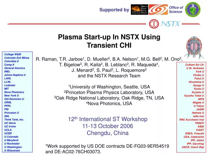
Office of Science Supported by College W&M Colorado Sch Mines Columbia U Comp-X General Atomics INEL Johns Hopkins U LANL LLNL Lodestar MIT Nova Photonics New York U Old Dominion U ORNL PPPL PSI Princeton U SNL Think Tank, Inc. UC Davis UC Irvine UCLA UCSD U Colorado U Maryland U Rochester U Washington U Wisconsin Culham Sci Ctr U St. Andrews York U Chubu U Fukui U Hiroshima U Hyogo U Kyoto U Kyushu U Kyushu Tokai U NIFS Niigata U U Tokyo JAERI Hebrew U Ioffe Inst RRC Kurchatov Inst TRINITI KBSI KAIST ENEA, Frascati CEA, Cadarache IPP, Jülich IPP, Garching ASCR, Czech Rep Plasma Start-up In NSTX Using Transient CHI R. Raman, T.R. Jarboe1, D. Mueller2, B.A. Nelson1, M.G. Bell2, M. Ono2, T. Bigelow3, R. Kaita2, B. Leblanc2, R. Maqueda4, J. Menard2, S. Paul2, L. Roquemore2 and the NSTX Research Team 1University of Washington, Seattle, USA 2Princeton Plasma Physics Laboratory, USA 3Oak Ridge National Laboratory, Oak Ridge, TN, USA 4Nova Photonics, USA 12th International ST Workshop 11-13 October 2006 Chengdu, China *Work supported by US DOE contracts DE-FG03-9ER54519 and DE-AC02-76CH03073.
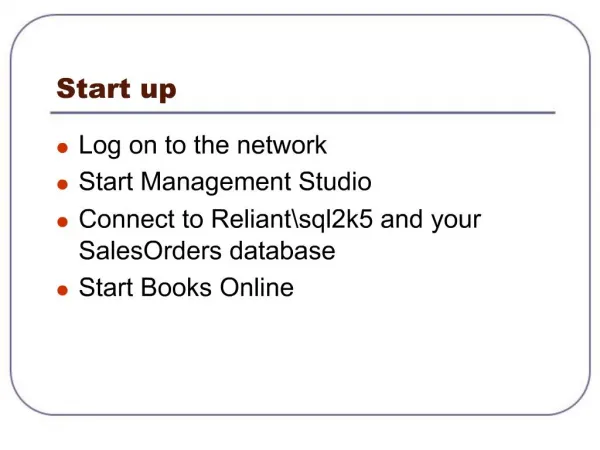
Outline • Motivation for solenoid-free plasma startup • Implementation of Coaxial Helicity Injection (CHI) in NSTX • Requirements for Transient CHI • Experimental results from NSTX • Brief summary of HIT-II results • Summary and Conclusions
Solenoid-free plasma startup is essential for the viability of the Spherical Tokamak (ST) concept • Elimination of the central solenoid simplifies the engineering design of tokamaks (Re: ARIES AT & RS) • CHI is capable of both plasma start-up and edge current in a pre-established diverted discharge - Edge current profile for high beta discharges
Implementation of CHI in NSTX Transient CHI: Expect axisymmetric reconnection at the injector to result in formation of closed flux surfaces
Requirements for optimizing Transient CHI • Bubble burst current* • Volt-seconds to replace the toroidal flux • For 600 mWb, at ~500V need ~1 ms just for current ramp-up • Energy for peak toroidal current • Energy for ionization of injected gas and heating to 20eV (~50eV/D) • For 2 Torr.L injected, need ~2kJ * T.R. Jarboe,"Formation and steady-state sustainment of a tokamak by coaxial helicity injection," Fusion Technology15, 7 (1989).
Capacitor bank used in Transient CHI Experiments • 50 mF (10 caps), 2 kV • Operated reliably at up to 1.75kV • Produced reliable breakdown at ~ 1/10th the previous gas pressure (20 Torr.Liter used in 2004) • Constant voltage application allowed more precise synchronization with gas injection • EC-Pi and gas injection below divertor used for Pre-ionization assist
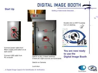
Improved pre-ionization to a level that results in injected gas 10 times less than in 2004 Shot 116565 • Novel pre-ionization system • Injects gas and 10-20kW of 18GHz ECH in a cavity below the lower divertor gap • Successfully tested, achieved discharge generation at injected gas amount of < 2 Torr.Liter • Fast Crowbar system • Rapidly reduces the injector current after the CHI discharge has elongated into the vessel. EC-Pi glow along the center stack The small glow shown by the arrow is in the gap between the lower divertor plates and it is produced solely by EC-Preionization of the gas injected below the lower divertor plates. No voltage is applied. Divertor gap Shot 116570 ECH: T. Bigelow (ORNL)
6 ms 8 ms 10 ms 12 ms 15 ms 17 ms Closed flux current generation by Transient CHI • Plasma current amplified many times over the injected current. • The sequence of camera images shows a fish eye image of the interior of the NSTX vacuum vessel. The central column is the center stack, which contains the conventional induction solenoid. The lower bright region seen at 6ms is the injector region. Hiroshima University (N. Nishino) Camera Images: R. Kaita (PPPL)
Discharges without an absorber arc show high current multiplication ratios (Ip / Iinj) of 60
Dramatic improvement in closed flux current generation from 2005 2006 discharges operated at higher capacitor bank voltage and higher toroidal field LRDFIT (J. Menard)
Electron temperature and density profiles become less hollow with time Profile becomes less hollow with time Plasma and Injector current 120814: Black: 8ms, Red: 12ms 120842: Black: 8ms, Red: 10ms Thomson (B. LeBlanc)
Data indicates that ~200kW of ECH would increase Te to ~100eV • Thomson scattering data indicates Te drops to 50% in 3-5ms TauE ~ 4ms • Zero-D estimates indicate 200kW ECH would increase Te ~ 60eV in 8ms and 100eV in 20ms, assuming TauE does not increase. • Consistent with Radiated power levels of <100kW • Consistent with low electron densities of ~2x10¹⁸m-3, for impurity burn through. Li a possibility for controlling Oxygen.
Some discharges persist for as long as the equilibrium coil currents are maintained Fast camera: R. Maqueda
Movie of a high current discharge Fast Camera: R. Maqueda & L. Roquemore
Favorable scaling with machine size Attainable current multiplication is given as , For similar values of BT, So current multiplication in NSTX should be 10x HIT-II, which is observed Next step STs would have about 10x the toroidal flux in NSTX, Which means current multiplication ratios in excess of 100 is not unrealistic in larger STs Potential for high current multiplication in larger STs
Allowable injector currents determined by maximum voltage Assuming constant , For similar values of , at the same voltage, in HIT-II is about 10 times higher than in NSTX Consistent with ~15-20kA on HIT-II vs ~2kA in NSTX Also consistent with the bubble burst relation, Which requires 10x more current in HIT-II than in NSTX 10x more injector flux of that in present NSTX 60kA experiments with 10x more injector flux leads to >2MA startup currents with 20kA injector current in future larger machines.
Full 2kV capability in NSTX would increase Ip ~ 300kA Best results from NSTX 2005 and 2006 HIT-II data: R. Raman, T.R. Jarboe et al., Nuclear Fusion, 45, L15-L19 (2005) Voltage, flux optimization allowed HIT-II to increase closed flux current as capacitor charging voltage was increased
Record non-inductive plasma startup currents in a tokamak (160kA in NSTX) verifies high current feasibility of CHI for plasma startup applications The significance of these results are: • demonstration of the process in a vessel volume thirty times larger than HIT-II on a size scale more comparable to a reactor, • a remarkable multiplication factor of 60 between the injected current and the achieved toroidal current, compared to six in previous experiments, • results were obtained on a machine designed with mainly conventional components and systems, • indicate favorable scaling with machine size. • NSTX high current discharges not yet optimized • Extension to ~300kA should be possible at 2kV • Future experiments to explore coupling to OH • 200kW ECH to heat the CHI plasma • Coupling to RF and NBI