Download
1 / 11
110 likes | 119 Views
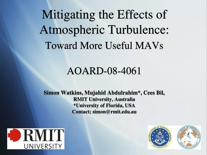
Mitigating the Effects of Atmospheric Turbulence: Toward More Useful MAVs AOARD‑08-4061 Simon Watkins, Mujahid Abdulrahim*, Cees Bil, RMIT University, Australia *University of Florida, USA Contact; simon@rmit.edu.au. The Challenge: Maintain Steady MAV Flight in Atmospheric Turbulence.

E N D
Mitigating the Effects of Atmospheric Turbulence:Toward More Useful MAVsAOARD‑08-4061Simon Watkins, Mujahid Abdulrahim*, Cees Bil,RMIT University, Australia*University of Florida, USAContact; simon@rmit.edu.au
The Challenge: Maintain Steady MAV Flight in Atmospheric Turbulence MAVs will gain information when there is no direct line of sight, thus will mainly be used in cities, or other complex terrain, where ambient turbulence levels are high. The above depiction illustrates potential roll and pitch inputs that natural fliers have evolved to cope with, but which remain a significant challenge to MAVs, particularly as their scale reduces. Note: • A standard size person (presumably with standard size lungs) • Complexity – significant changes in small distances • Vorticity (especially at top, 1/3rd from start and at end)
Overall Objective: Pursue passive and active strategies to reduce the disturbances to MAVs when flying in turbulent wind environments as found close to the ground in complex terrains. Methods: Utilise prior outdoor measurements to replicate turbulence in tunnels of varying sizes and perform two types of experiments: 1) Fundamental fluid-mechanic experiments, measuring dynamic forces and pressures on airfoils 2) Flying experiments, where piloted, instrumented MAVs are flown in a large scale flying facility whilst measuring MAV motions, control inputs and upstream flow conditions
Facilities and Equipment 2x3x9m Tunnel, replicates small-scale turbulence via grids to ~14% intensity for fluid-mechanic measurements on airfoils and MAVs Flight test tunnel, replicates large-scale turbulence up to ~25% intensity for flying MAV experiments, with photogrammetry & real-time upstream flow documentation Micro dynamic force balance (MDFB), flight data loggers, 4 robust turbulence probes, velocity & pressure transducers fixed wing and rotary MAVs, (various scales) MDFB Probes Flapping MAV on MDFB
Time-Averaged -Cp Distribution • Suction surface pressure distribution as a function of incidence • Data obtained from central span chordwise pressure taps on 1.9% thick, 2:1 AR SLS aerofoil with integral pressure taps. Suction side results only – colour indicates amplitude of negative Cp • Effect of increasing ambient turbulence level is shown to delay the onset of stall, and reduce separation Turbulence=1.8% Turbulence=6.2% Pressure tap locations Turbulence=12.8%
Standard Deviation Cp Distribution • Standard deviation gives a indication of the magnitude and location of the transient flow region, such as flow separation and reattachment zone. Note change in scaling of amplitude • The effect of increased turbulence is to keep this location closer to the leading edge, and to increase its intensity Turbulence=1.8% Turbulence=6.2% Turbulence=12.8%
Turbulence = 1.8% Turbulence = 14% α=2° Spectrograms reveal effects of turbulence on laminar separation bubble α=6° α=8° α=10° α=12°
Flying Experiments • Tunnel top section configured to replicate IAS of 8m/s into a light wind, city conditions as well as smooth flow (bottom picture) in car test section • Attempting steady flight, on-board logging of 6 DOF and control inputs in smooth and turbulent flow • 6 video cameras with reflective markers on MAVs for photogrammetry • Upstream velocity (u,v,w) measured simultaneously at 4 spanwise locations at 1250Hz • Fixed wing MAVs and 3 scales of rotary wing • Parametric variation of span, CG location, MOI and mass
Flight test videos • See www.project240.net/mav_turbulence
Comments • Fixed wing - low pilot workload in smooth flow, high in turbulent (C-H*: 5-10), frequent terminal departure, highest sensitivity in roll • Rotary wing - high pilot workload under smooth flow, only small increase in turbulent flow (C-H: 3-4), all successful landings, lowest sensitivity in roll • Parametric studies, flapping and active control– ongoing research *Cooper-Harper rating – used to evaluate handling qualities of aircraft
Future Possibilities • Further dynamic surface pressure and force measurements on airfoils to understand physics and flight inputs and as potential inputs for gust alleviation (feeling the air) • Flying instrumented birds and insects in conjunction with Oxford Flight Group to gain insight in to natural mechanisms for gust alleviation. • Fixed vs rotary vs flapping - efficiency and gust response? + = ?