Download
1 / 26
420 likes | 852 Views
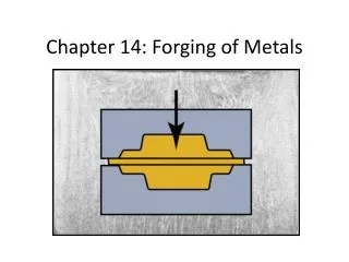
Chapter 14 Metal-Forging Processes and Equipment.

E N D
FORGINGthe work piece is shaped by compressive forces applied through various dies and toolingCold forgingHot forgingCold forging requires more force than hot forging due to the higher strength of the work pieceUnlike rolling, it produces discrete parts
TYPICAL PRODUCTSshaftsgearshand toolsturbine bladesfarm equipment
FIGURE 14.1 (a) Illustration of the steps involved in forging a knife. (b) Landing-gear components for the C5A and C5B transport aircraft, made by forging. (c) General view of a 445-MN (50,000-ton) hydraulic press.Source: (a) Courtesy of Mundial, LLC. (b) and (c) Courtesy of Wyman-Gordon Company.
Forged parts have good strength and toughness because metal flow and grain structure can be controlled
FIGURE 14.2 Schematic illustration of a part (dragline chain link, approximately 2 m long) made by three different processes and showing grain flow. Each process has its own advantages and limitations regarding external and internal characteristics, material properties, dimensional accuracy, surface finish, and the economics of production. Source: Courtesy of the Forging Industry Association.
OPEN DIE FORGINGPAN CAKING OR BARRELINGdue to 1. Friction at the interface2. Cold at interface and hot in the middle so the resistance to deformation is greater at the ends
FIGURE 14.3 (a) Solid cylindrical billet upset between two flat dies. (b) Uniform deformation of the billet without friction. (c) Deformation with friction; note barreling of the billet caused by friction forces at the billet–die interfaces.
COGGING OPERATIONthickness is reduced by successive forging steps
FIGURE 14.4 (a) Schematic illustration of a cogging operation on a rectangular bar. Blacksmiths use this process to reduce the thickness of bars by hammering the part on an anvil; reduction in thickness is accompanied by barreling. (b) Reducing the diameter of a bar by open-die forging; note the movements of the dies and the workpiece. (c) The thickness of a ring being reduced by open-die forging.
IMPRESSION DIE FORGINGWork piece takes shape of die cavity while being shaped between two shaped diesUsually takes place at elevated temperatures
FIGURE 14.6 (a) through (d) Stages in impression-die forging of a solid round billet; note the formation of flash, which is excess metal that is subsequently trimmed off. (e) Standard terminology for various features of a forging die.
FIGURE 14.9 Trimming flash from a forged part; note that the thin material at the center (slug) is removed by punching.
FIGURE 14.10 Comparison of (a) closed-die forging with flash and (b) precision or flashless forging of a round billet. Source: After H. Takemasu, V. Vazquez, B. Painter, and T. Altan.
FIGURE 14.11 (a) Schematic illustration of the coining process; the earliest coins (see TABLE I.2) were made by open-die forging and lacked precision and sharp details. (b) An example of a modern coining operation, showing the coins and tooling; note the detail and superior surface finish that can be achieved in this process. Source: Courtesy of C & W Steel Stamp Company Inc.
FIGURE 14.12 (a) Heading operation to form heads on fasteners, such as nails and rivets. (b) Sequence of operations in producing a typical bolt head by heading.
FIGURE 14.13 (a) Examples of piercing operations. (b) A pierced round billet showing grain-flow pattern (see also Fig. 14.2c). Source: Courtesy of Ladish Co., Inc.
FIGURE 14.14 (a) The stepped pin used in Case Study 14.1. (b) Illustration of the manufacturing steps used to produce the stepped pin. Source: Courtesy of National Machinery, LLC.
TABLE 14.3 Forgeability of Metals, in Decreasing Order (See also TABLE 15.1)
FIGURE 14.17 Examples of defects in forged parts. (a) Laps due to web buckling during forging; web thickness should be increased to avoid this problem. (b) Internal defects caused by an oversized billet; die cavities are filled prematurely, and the material at the center flows past the filled regions as the dies close.
FIGURE 14.20 (a) Schematic illustration of a servo press, with the power source and transmission components highlighted. (b) An example of a servo press, with a 23,000 kN (2500 ton) capacity.Source: Courtesy of Aida Engineering, Inc.