Download
1 / 18
180 likes | 185 Views
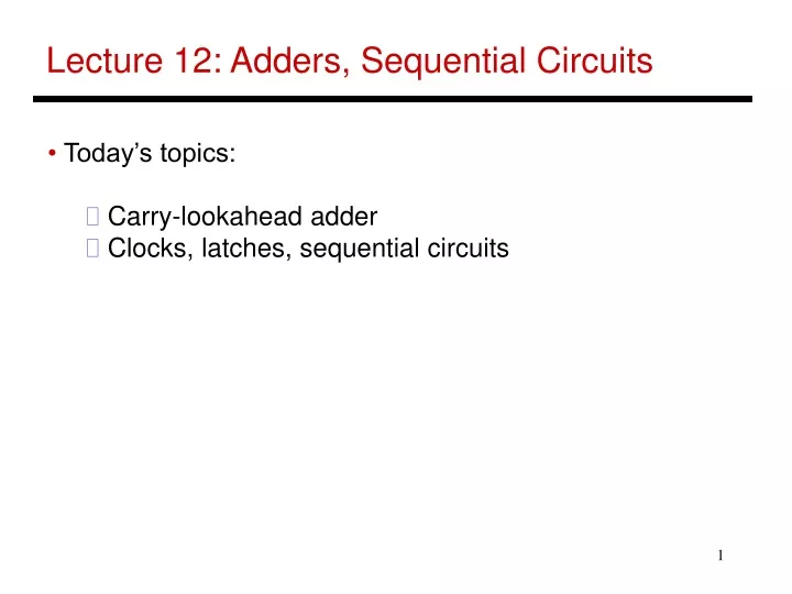
Lecture 12: Adders, Sequential Circuits. Today’s topics: Carry-lookahead adder Clocks, latches, sequential circuits. Incorporating slt. Perform a – b and check the sign New signal (Less) that is zero for ALU boxes 1-31 The 31 st box has a unit to detect overflow and

E N D
Lecture 12: Adders, Sequential Circuits • Today’s topics: • Carry-lookahead adder • Clocks, latches, sequential circuits
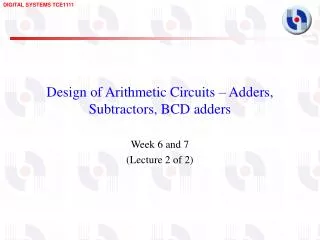
Incorporating slt • Perform a – b and check the sign • New signal (Less) that is zero for ALU boxes 1-31 • The 31st box has a unit to detect overflow and sign – the sign bit serves as the Less signal for the 0th box Source: H&P textbook
Incorporating beq • Perform a – b and confirm that the result is all zero’s Source: H&P textbook
Control Lines What are the values of the control lines and what operations do they correspond to? Source: H&P textbook
Control Lines What are the values of the control lines and what operations do they correspond to? Ai Bn Op AND 0 0 00 OR 0 0 01 Add 0 0 10 Sub 0 1 10 SLT 0 1 11 NOR 1 1 00 Source: H&P textbook
Speed of Ripple Carry • The carry propagates thru every 1-bit box: each 1-bit box sequentially implements AND and OR – total delay is the time to go through 64 gates! • We’ve already seen that any logic equation can be expressed as the sum of products – so it should be possible to compute the result by going through only 2 gates! • Caveat: need many parallel gates and each gate may have a very large number of inputs – it is difficult to efficiently build such large gates, so we’ll find a compromise: • moderate number of gates • moderate number of inputs to each gate • moderate number of sequential gates traversed
Computing CarryOut CarryIn1 = b0.CarryIn0 + a0.CarryIn0 + a0.b0 CarryIn2 = b1.CarryIn1 + a1.CarryIn1 + a1.b1 = b1.b0.c0 + b1.a0.c0 + b1.a0.b0 + a1.b0.c0 + a1.a0.c0 + a1.a0.b0 + a1.b1 … CarryIn32 = a really large sum of really large products • Potentially fast implementation as the result is computed by going thru just 2 levels of logic – unfortunately, each gate is enormous and slow
Generate and Propagate Equation re-phrased: Ci+1 = ai.bi + ai.Ci + bi.Ci = (ai.bi) + (ai + bi).Ci Stated verbally, the current pair of bits will generate a carry if they are both 1 and the current pair of bits will propagate a carry if either is 1 Generate signal = ai.bi Propagate signal = ai + bi Therefore, Ci+1 = Gi + Pi . Ci
Generate and Propagate c1 = g0 + p0.c0 c2 = g1 + p1.c1 = g1 + p1.g0 + p1.p0.c0 c3 = g2 + p2.g1 + p2.p1.g0 + p2.p1.p0.c0 c4 = g3 + p3.g2 + p3.p2.g1 + p3.p2.p1.g0 + p3.p2.p1.p0.c0 Either, a carry was just generated, or a carry was generated in the last step and was propagated, or a carry was generated two steps back and was propagated by both the next two stages, or a carry was generated N steps back and was propagated by every single one of the N next stages
Divide and Conquer • The equations on the previous slide are still difficult to implement as logic functions – for the 32nd bit, we must AND every single propagate bit to determine what becomes of c0 (among other things) • Hence, the bits are broken into groups (of 4) and each group computes its group-generate and group-propagate • For example, to add 32 numbers, you can partition the task as a tree . . . . . . . . . . . . . . . . . . . . .
P and G for 4-bit Blocks • Compute P0 and G0 (super-propagate and super-generate) for the first group of 4 bits (and similarly for other groups of 4 bits) P0 = p0.p1.p2.p3 G0 = g3 + g2.p3 + g1.p2.p3 + g0.p1.p2.p3 • Carry out of the first group of 4 bits is C1 = G0 + P0.c0 C2 = G1 + P1.G0 + P1.P0.c0 C3 = G2 + (P2.G1) + (P2.P1.G0) + (P2.P1.P0.c0) C4 = G3 + (P3.G2) + (P3.P2.G1) + (P3.P2.P1.G0) + (P3.P2.P1.P0.c0) • By having a tree of sub-computations, each AND, OR gate has few inputs and logic signals have to travel through a modest set of gates (equal to the height of the tree)
Example Add A 0001 1010 0011 0011 B 1110 0101 1110 1011 g 0000 0000 0010 0011 p 1111 1111 1111 1011 P 1 1 1 0 G 0 0 1 0 C4 = 1
Carry Look-Ahead Adder • 16-bit Ripple-carry takes 32 steps • This design takes how many steps? Source: H&P textbook
Clocks • A microprocessor is composed of many different circuits that are operating simultaneously – if each circuit X takes in inputs at time TIX, takes time TEX to execute the logic, and produces outputs at time TOX, imagine the complications in co-ordinating the tasks of every circuit • A major school of thought (used in most processors built today): all circuits on the chip share a clock signal (a square wave) that tells every circuit when to accept inputs, how much time they have to execute the logic, and when they must produce outputs
Clock Terminology Rising clock edge Cycle time Falling clock edge 4 GHz = clock speed = 1 = 1 . cycle time 250 ps
Sequential Circuits • Until now, circuits were combinational – when inputs change, the outputs change after a while (time = logic delay thru circuit) Combinational Circuit Combinational Circuit Outputs Inputs • We want the clock to act like a start and stop signal – a “latch” is a storage device that separates these circuits – it ensures that the inputs to the circuit do not change during a clock cycle Clock Clock Combinational Circuit Combinational Circuit Outputs Inputs Latch Latch
Sequential Circuits • Sequential circuit: consists of combinational circuit and a storage element • At the start of the clock cycle, the rising edge causes the “state” storage to store some input values • This state will not change for an entire cycle (until next rising edge) • The combinational circuit has some time to accept the value of “state” and “inputs” and produce “outputs” • Some of the outputs (for example, the value of next “state”) may feed back (but through the latch so they’re only seen in the next cycle) Inputs State Clock Outputs Inputs Combinational Cct
Title • Bullet