Download
1 / 15
160 likes | 267 Views
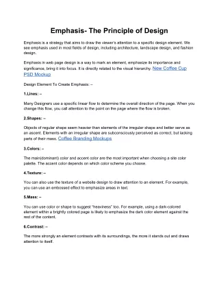
Outline. Purpose of work Design principle of the proton beam window (from 2003) Location of the PBW in ESS Assumed beam profile Analytical calculations CFD calculations for water cooling CFD calculations for helium cooling Conclusion and outlook. Purpose of Work.

E N D
Outline • Purpose of work • Design principle of the proton beam window (from 2003) • Location of the PBW in ESS • Assumed beam profile • Analytical calculations • CFD calculations for water cooling • CFD calculations for helium cooling • Conclusion and outlook
Purpose of Work • - In 2003 a novel type of Proton Beam Window (PBW) for high beam current densities was proposed by Juelich. Due to the end of the ESS-Work in 2003 only very rough investigations were possible. • - This work picks up the 2003 design idea adjusted to the actual proton beam parameters for ESS. • - Providing more in depth calculation for water and even He cooling. • - Optimize the design to minimize stress. • - Show potential of this design. • - Presentation shows current status of ongoing work
Design principle of the PBW • Reduce wall thickness by reducing radius to minimize heat deposited in window • proof of manufacturing sample
The Proton Beam Window in the ESS Target Station • - The PBW separates the accelerator vacuum from the atmosphere around the target. • - The atmosphere around the target could either be a rough vacuum or helium at atmospheric pressure. • - Distance from the target is mainly defined by accessibility for handling. Most likely more that 1.5 meter. • - Therefore the beam footprint at the PBW <> beam footprint at the Target. • - ESS Proton beam line design for the last few meters before the target not fixed yet. • - Most likely the footprint at the PBW will be smaller (higher peak current density).
The Proton Beam Window in the ESS Target Station • Collimator ? • PBW • Target ~ 1.5 m • Beam Envelope ESS 2003 LP 2011 ESS design approach for rotating Target
Assumed beam and heat deposit profile • Since beam profile at target and even more at the PBW is not fixed we took the following conservative assumption: • Beam size to be double Gaussian with ± 2· within footprint of 200 x 60 mm (same size as beam on target), assuming no shrinking of the footprint at the PBW. • Most likely the beam footprint will be smaller at the position of the PBW. Therefore the current density (and thus peak current density) is assumed to be about double compared to the value at the target. • Mathematically this corresponds to a 10 MW proton beam.
Design Loads and Boundary Conditions • Peak heat deposition by protons in the tungsten target was calculated (Sordo et al.) to be ~ 3 W/mm³. Scaling by density (aluminum vs. tungsten) leads to 0.43 W/mm³. We conservatively doubled to 1 W/mm³ • Pressure of cooling medium was chosen to be 10 bars for water and 40 bars for helium • Pressure difference over windowwas chosen to be 1 bar • Window material Al 6061 T6 Sordo et al.
Heat load used for Calculation Gaussian profile =2, P0 = 1kW/cm³ (± 2· within beam footprint) Al 6061 – T6
Analytical calculations (VDI Wärmeatlas) he / 40 bars / 40 °C water / 10 bars / 40 °C
CFD results for Water cooling (Tin = 40°) mean velocity 3.2 m/s
Stress for Water Cooling max. stress in beam region ~35 MPa point of highest stress
CFD results for Helium cooling (Tin = 40°) mean velocity 54 m/s
Stress for Helium Cooling max. stress in beam region ~116 MPa (inside pipe)
Conclusions and Outlook • - Even with very conservative assumptions this type of PBW should be good for more than 5 MW beam power if cooled by water. • - Helium cooling seems to be possible. Values for temperature and stress are still acceptable. Helium cooling would be beneficial in case of cooling medium leaking into the accelerator. • - There is still room for optimization of the design . • - We will look into alternative materials (to allow higher temperatures for Helium cooling) • - As soon as beam foot print data will be available for ESS we could significantly reduce conservatism. Thank you for your attention