Download
1 / 37
380 likes | 549 Views
Components of TCA. Injector Chamber Nozzle. Design Process. The first step in the design was to pick propellants LOX – propylene chosen for several reasons Customer has experience and access Allow for partial self pressurization of propellant tanks

E N D
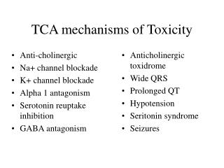
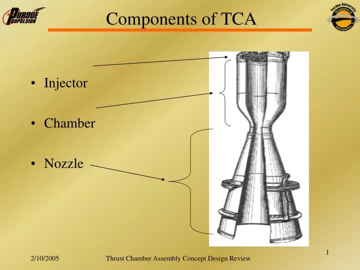
Components of TCA • Injector • Chamber • Nozzle Thrust Chamber Assembly Concept Design Review
Design Process • The first step in the design was to pick propellants • LOX – propylene chosen for several reasons • Customer has experience and access • Allow for partial self pressurization of propellant tanks • The mixture ratio is specified by CSULB based on the ratio that will give the best operability = 2.27. This allows for the propellant tanks to empty at the same rate • A chamber pressure must be chosen • 300 psi was chosen by the customer. • Current tanks can handle 450 psi 300 psi chamber pressure after losses • Cooling by passive means is possible (No dump or regenerative cooling required) Thrust Chamber Assembly Concept Design Review
Design Process • With the information available we run the NASA thermochemistry code to obtain some useful data: • Chamber Temp (Tc) = 6341 R • C* = 6044 ft/s • Exit pressure (pe) = 5.66 psi • Exit velocity (ve) = 9627.8 ft/s • Cfvac = 1.593 • Specific heat ratio γ = 1.1398 • Molecular weight = 21.313 • Ispvac = 327.6 s Thrust Chamber Assembly Concept Design Review
Design Process With this data we can continue with the design of the engine. We would like to use the equation that relates mass flow rate to force and Isp so first we need Cf at sea level, and then Isp at sea level and then finally mass flow rate through the engine. From NASA code Design parameters From NASA code Design parameter Thrust Chamber Assembly Concept Design Review
We know our O/F ratio so we can then split the mass flow into fuel and oxidizer: Design Process Where r is the mixture ratio The throat area is found with: We choose a contraction ratio of 2 to help with combustion stability Thrust Chamber Assembly Concept Design Review
We use the design parameter L* to find the size of the combustion chamber. We used an L* of 42.5 in because it has worked successfully in the past with RP-1. Design Process This is the volume needed Length of converging section with θc the converging half angle Volume that the converging section makes Use a cylinder to make the rest of the volume Thrust Chamber Assembly Concept Design Review
Injector design pressure loss is 70 psi. We use .2*Pc = 60 psi for the drop across the orifices Area for injection is found with the pressure drop from the manifold to the chamber with: Design Process Cd is discharge coefficient = .80 We need to select hole sizes based on drill bits that can be purchased. By selecting the number of orifices that we want we can find the hole sizes that we need. Going back we can find the new mass flows and actual O/F. Thrust Chamber Assembly Concept Design Review
Design Requirements – Chamber • L* = 42.5 in • Should withstand heat flux for burn time • Should withstand any transient pressure • Should not be overly complicated (Cheap to build) • Cannot use regenerative cooling because of lack of pressure budget • Use ablative liner and film cooling or O/F bias. • Convergence ratio of 2 • Need to be able to flange onto injector Thrust Chamber Assembly Concept Design Review
Design Specs - Chamber • Chamber Diameter = 3.69 in • Length of chamber = 20.73 in • Length of converging section ≈ .64 in • Diameter of throat = 2.61 in Thrust Chamber Assembly Concept Design Review
Current Chamber Design • Put drawing here Thrust Chamber Assembly Concept Design Review
Design Requirements – Nozzle NASA Dryden • Expansion ratio = 8 • 75% bell to assist in weight reduction • Manufacturing must be taken into consideration • Conical nozzle used to be cheaper to manufacture • CNC manufacturing has reduced cost of bell nozzle • Uncooled Thrust Chamber Assembly Concept Design Review
Design Specs - Nozzle • Length of nozzle • 8.91 in (15° cone) • 7.13 in (80% bell) • 75% Bell • Lower Weight • Better Performance Bell Nozzle on Pump-Fed LRE Thrust Chamber Assembly Concept Design Review
Current Nozzle Design Thrust Chamber Assembly Concept Design Review
Design Requirements - Injector • By far the most complicated part of design • ΔP = 70 psi • Shouldn’t melt or scorch • Provide combustion stability • No inter-propellant seals • Total flow rate = 8.45 lbm/s • Ox flow rate = 5.87 lbm/s • Fuel Flow rate = 2.58 lbm/s Thrust Chamber Assembly Concept Design Review
O-F-O Impinging Injector • Injector provides for propellant mixing by impinging jets. Two oxidizer jets impinge on one fuel jet. O F O Fan Thrust Chamber Assembly Concept Design Review
O-F-O Injector • Well known design process • Better performance compared to pintle • Allows for O/F biasing against wall and film cooling • Propellants are well suited for this option • SG propylene = .5 • SG LOX = 1.14 • O/F = 2.27 Thrust Chamber Assembly Concept Design Review
Injector Sizing • 18 – triplets • 18 film cooling elements • Oversize outboard oxidizer element to ensure jets stay away from the wall • Impingement point length/ diameter of orifice should be ~ 5 • Bore length/diameter of orifice should be > 3.5 to ensure Cd = .80 • Manifolds – 10*area of orifices they feed Thrust Chamber Assembly Concept Design Review
Injector Concept Thrust Chamber Assembly Concept Design Review
Injector Concept Thrust Chamber Assembly Concept Design Review
Injector Concept • Put the picture here Thrust Chamber Assembly Concept Design Review
Injector Performance Analysis • With these sizes: Stream Lengths Bore Lengths Thrust Chamber Assembly Concept Design Review
Injector Lengths Thrust Chamber Assembly Concept Design Review
Manifold Sizes Thrust Chamber Assembly Concept Design Review
Manifold Sizes Thrust Chamber Assembly Concept Design Review
Manifold Sizes • Aox,in = .08165 in2 • Aox,out = .01437 in2 • Afuel = .01452 in2 • Afilm = .00226 in2 • Flow Area/ Injection Area • Oxin = 2.296 • Oxout = 7.738 • Fuel = 9.043 • Film = 33.186 Thrust Chamber Assembly Concept Design Review
Injector performance • Velocities: • Ox = 88.35 ft/s • Fuel = 120.45 ft/s • Momenta • Ox_out = 222 lb-in/s2 • Ox_in = 210 lb-in/s2 • Fuel = 224 lb-in/s2 0.9911 : 1.0000 : 0.9375 Thrust Chamber Assembly Concept Design Review
Injector Fill Times Fill times tox= .05 sec tfuel= .002 sec Volumes Vox = 7.13508 in3 Vf = .26875 in3 Volumetric flows Qox = 142 in3/s Qf = 118.5 in3/s Thrust Chamber Assembly Concept Design Review
Combustion Stability Stable Unstable Thrust Chamber Assembly Concept Design Review
Current Concept Summary • Injector: O-F-O Injector • Chamber: Ablative Lining • Nozzle: 80% Bell Picture here Thrust Chamber Assembly Concept Design Review
Numbers Summary Thrust Chamber Assembly Concept Design Review
Numbers Thrust Chamber Assembly Concept Design Review
Numbers Thrust Chamber Assembly Concept Design Review
Numbers Thrust Chamber Assembly Concept Design Review
Adiabatic Flame Temperature vs. O/F Ratio Thrust Chamber Assembly Concept Design Review
Cstar vs. O/F Ratio Thrust Chamber Assembly Concept Design Review
Ivac vs. O/F Ratio Thrust Chamber Assembly Concept Design Review
Thrust Coefficient vs. O/F Ratio Thrust Chamber Assembly Concept Design Review