Download

1 / 18
240 likes | 515 Views
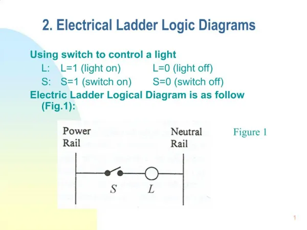
Lesson 02 Ladder Logic Simulation with OpenPLC Editor. Dr. David J. Coe Electrical and Computer Engineering Department University of Alabama in Huntsville coed@uah.edu. Outline. Review Simulation of Ladder Logic Suggested Reading Hands-On Laboratory Exercise #2. Review.

E N D
Lesson 02Ladder Logic Simulation with OpenPLC Editor Dr. David J. Coe Electrical and Computer Engineering Department University of Alabama in Huntsville coed@uah.edu
Outline • Review • Simulation of Ladder Logic • Suggested Reading • Hands-On Laboratory Exercise #2
Sample Ladder Logic in OpenPLC Editor LED lights whenever PB2 is pressed LED lights for 2 sec after PB1 is pressed LED is off otherwise
Ladder Logic Simulation - 1 Start OpenPLC Editor simulator
Ladder Logic Simulation - 2 Select instance to debug (Makes energized components visible in your ladder logic)
Ladder Logic Simulation - 3 Select variables to view
Ladder Logic Simulation - 4 • Variable values appear on right • PB1 and PB2 false wires to right not energized (black) • LED false no light emitted
Ladder Logic Simulation - 5 Force PB1 to true to simulate button press (right-click on PB1 to see menu)
Ladder Logic Simulation - 6 Green path through PB1 and LED from left rail to right rail LED coil now energized light emitted
Ladder Logic Simulation - 7 Force PB1 to false to simulate button not pressed
Ladder Logic Simulation - 8 LED coil will be de-energized after 2 sec LED stops emitting light Note: Hit STOP sign to end simulation
Suggested Reading • The OpenPLC Project https://www.openplcproject.com/ • Tommy Morris – Six SCADA Modules https://clark.center/details/tommy_morris/Six%20SCADA%20Modules
Laboratory Exercise #2 Instructions - 1 • Objective • Learn how to use OpenPLC Editor’s simulator to verify correctness of a Ladder Logic program
Laboratory Exercise #2 Instructions - 2 • Use OpenPLC Editor to simulate the First Project Ladder Logic as described at the URL https://www.openplcproject.com/reference-your-first-project • Force each input PB1 and PB2 through all possible combinations of input states https://www.openplcproject.com/reference-your-first-project
Laboratory Exercise #2 Instructions - 3 • Sample Deliverables • Screenshots of Ladder Logic program simulation including forcing of PB1 and PB2 to have all possible combinations of states • Completed table as shown below