Download

1 / 27
270 likes | 292 Views
Learn how to make an LED blink using Arduino. This tutorial covers the basics of Arduino programming and demonstrates how to control an LED with code.

E N D
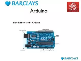
Arduino Beginnings Dr. Veton Kepuska Based on the https://www.instructables.com/class/Arduino-Class/
Blink // Pin 13 has an LED connected on most Arduino boards. // give it a name: intled = 13; // the setup routine runs once when you press reset: void setup() { // initialize the digital pin as an output. pinMode(led, OUTPUT); } // the loop routine runs over and over again forever: void loop() { digitalWrite(led, HIGH); // turn the LED on (HIGH is the voltage level) delay(1000); // wait for a second digitalWrite(led, LOW); // turn the LED off by making the voltage LOW delay(1000); // wait for a second }
Comments: // // Pin 13 has an LED connected on most Arduino boards. // give it a name: This is just a comment, meant to help us understand the program. It is strongly recommended you to get into the habit of heavily commenting your code, and reading the comments in each of the examples we use in this class.
int led = 13; You can think of a variable as a bucket for some information. Variables, like buckets, have sizes and shapes to hold different kinds of information. Variables also have names, like a mandatory label on the bucket. This line of code defines a variable of type int, which means integer. It's label is led but could just as easily be "MyLEDPin" or any single word (letters and numbers only, case sensitive) because this part of the variable declaration is up to you. I strongly advise using descriptive names for your variables so you can keep track of what your program is doing! After the line of code above, any time we see "led" in the program will be swapped out for the number 13. This is handy for configurations like ours, where we want a way to reference which pin the LED is connected to, over and over, but if the wiring changes we'll only have to update it on one place in the code.
// the setup routine runs once when you press reset: void setup() { As the comment suggests, anything between this line and the closing curly brace } is part of the setup, a section of code that runs once per session. Code inside the setup executes one time when your board first powers up, or when you press the Arduino's reset button.
// initialize the digital pin as an output. pinMode(led, OUTPUT); } Pins 0-13 on your Arduino board are digital i/o pins, which means they can be either inputs or outputs. pinMode(); is a function, a shorthand way to refer to subset of commands "under the hood,". Arduino shows you it recognizes certain elements of code by changing its text color. If ever a keyword isn't changing color as you type it in Arduino, you probably have a misspelling, capitalization error, or other typo. These pieces of information passed to functions are called arguments. Since the variable led will serve up its contents anytime you type it, the pin number passed to pinMode(); is 13, and the state is OUTPUT. This sets up pin 13 to control an LED, and the curly brace closes the setup.
// the loop routine runs over and over again forever:void loop() { This is the main part of an Arduino sketch, where actions like checking input pins and controlling output pins usually happen. Everything between this line and its closing curly brace } will occur on repeat until the board loses power.
// turn the LED on (HIGH is the voltage level) digitalWrite(led, HIGH); First up in the loop is a function called digitalWrite();, which takes two pieces of information: a pin number, and a HIGH (on) or LOW (off) state. These pieces of information passed to functions are called arguments. Since the variable led will serve up its contents anytime you type it, the pin number passed to digitalWrite(); is 13, and the state is HIGH (on). This line of code causes the LED in your circuit to turn on.
// wait for a second delay(1000); delay(); is another one of Arduino's built-in functions. It pauses the program for an amount of time, written in milliseconds. This line of code pauses the program for 1000ms, or one second.
// turn the LED off by making the voltage LOW digitalWrite(led, LOW); As earlier, digitalWrite(); can turn an output pin on or off. This time it sets pin 13 LOW (off).
// wait for a second delay(1000);} This line pauses the program for one second, and the curly brace signifies the end of the loop, which begins again immediately. So to summarize, the program turns an LED on and off at one second intervals. Let's try switching up that interval. Modify the number of milliseconds in one or both of your delay(); statements. For instance you could create a more uneven blink:
Uneven blink void loop() { digitalWrite(led, HIGH); // turn the LED on (HIGH is the voltage level) delay(2000); // wait for two seconds digitalWrite(led, LOW); // turn the LED off by making the voltage LOW delay(500); // wait for a half second }
Fade • Copy/download the code from the example in your Arduino software examples under File -> Examples -> 01.Basics -> Fade.
Plug in and upload the sketch to your Arduino MEGA board and observe your LED fade on and off.
Code int led = 9; // the PWM pin the LED is attached to intbrightness = 0; // how bright the LED is intfadeAmount = 5; // how many points to fade the LED by // the setup routine runs once when you press reset: void setup() { // declare pin 9 to be an output: pinMode(led, OUTPUT); } // the loop routine runs over and // over again forever: void loop() { // set the brightness of pin 9: analogWrite(led, brightness); // change the brightness for next // time through the loop: brightness = brightness + fadeAmount; // reverse the direction of the fading // at the ends of the fade: if (brightness <= 0 || brightness >= 255){ fadeAmount= -fadeAmount; } // wait for 30 milliseconds to see the // dimming effect delay(30); }
pulse width modulation (PWM) • Lines 16 through 18 declare three variables used in the program. • The setup configures pin 9 as an output on line 23. • On line 29, the function analogWrite(); sets pin 9 to whatever the variable brightness is at the given time. • On line 32, brightness is incremented by 5 (fadeAmount). • Line 35 uses an if statement to check if brightness using comparison operators. If brightness is less than or equal to <= zero, or || greater than or equal to >= 255. If the statement is true, the code inside is executed, otherwise it's just skipped. So this code increases brightness until it reaches or exceeds 255, then sets fadeAmount to -5 and decrements brightness until it reaches zero (or dips below zero). • The delay at the end prevents the code from running so fast that you can't see the effect. Try changing the value of fadeAmount and upload the code to your board. How does changing this variable affect the appearance of the fading? • The Arduino board is only capable of generating digital signals (HIGH and LOW), but analogWrite(); simulates the appearance of brightnesses between on and off using pulse width modulation (PWM). The LED flashes on and off very quickly, and your eye interprets a dimmer light. The ratio of time the LED spends on vs. off determines how bright or dim the LED appears. • Only certain pins are capable of PWM, and they are labeled on the board, which we'll do in a later lesson.
RGB LEDs • Additive (light-based) color has three primary colors: red, green, and blue. Simultaneously controlling the brightness of one LED of each of these colors can create almost any color of light. • Color changing LEDs like those used in the final project work the same way, but the LEDs are all together in a very small package called an RGB LED. Let's build our own RGB LED from three 5mm LEDs in your kits. In the Adafruit kit recommended for this class, these three LEDs have clear lenses, so we'll have to plug them in to determine which LED is which. LEDs with clear lenses can be any color! If you're using a different kit, just find one red, one green, and one blue LED (clear or colored lens). Unplug your USB cable and swap out the red LED for one of the clear-lens LEDs, then plug the USB back in.
RGB Code /* * Code for cross-fading 3 LEDs, red, green and blue (RGB) * To create fades, you need to do two things: * 1. Describe the colors you want to be displayed * 2. List the order you want them to fade in * * DESCRIBING A COLOR: * A color is just an array of three percentages, 0-100, * controlling the red, green and blue LEDs * * Red is the red LED at full, blue and green off * int red = { 100, 0, 0 } * Dim white is all three LEDs at 30% * intdimWhite = {30, 30, 30} * etc. * * Some common colors are provided below, or make your own * * LISTING THE ORDER: * In the main part of the program, you need to list the order you want to colors to appear in, e.g. * crossFade(red); * crossFade(green); * crossFade(blue); * * Those colors will appear in that order, fading out of one color and into the next * * In addition, there are 5 optional settings you can adjust: * 1. The initial color is set to black (so the first color fades in), but you can set the initial color to be *any other color * 2. The internal loop runs for 1020 interations; the 'wait' variable sets the approximate duration * of a single crossfade. In theory, a 'wait' of 10 ms should make a crossFade of ~10 *seconds. In practice, the other functions the code is performing slow this down to ~11 *seconds on my board. YMMV. * 3. If 'repeat' is set to 0, the program will loop indefinitely. if it is set to a number, it will loop that * number of times, then stop on the last color in the sequence. (Set 'return' to 1, and * make the last color black if you want it to fade out at the end.) * 4. There is an optional 'hold' variable, which pasues the program for 'hold' milliseconds when a * color is complete, but before the next color starts. * 5. Set the DEBUG flag to 1 if you want debugging output to be sent to the serial monitor. * * The internals of the program aren't complicated, but they * are a little fussy -- the inner workings are explained below the main loop. * * April 2007, Clay Shirky <clay.shirky@nyu.edu> */
// Output intredPin = 9; // Red LED, connected to digital pin 9 intgrnPin = 10; // Green LED, connected to digital pin 10 intbluPin = 11; // Blue LED, connected to digital pin 11 // Color arrays int black[3] = { 0, 0, 0 }; int white[3] = { 100, 100, 100 }; int red[3] = { 100, 0, 0 }; int green[3] = { 0, 100, 0 }; int blue[3] = { 0, 0, 100 }; int yellow[3] = { 40, 95, 0 }; intdimWhite[3] = { 30, 30, 30 }; // etc. // Set initial color intredVal = black[0]; intgrnVal = black[1]; intbluVal = black[2]; int wait = 10; // 10ms internal crossFade delay; increase for slower fades int hold = 0; // Optional hold when a color is complete, before the next crossFade int DEBUG = 1; // DEBUG counter; if set to 1, will write values back via serial intloopCount = 60; // How often should DEBUG report? int repeat = 3; // How many times should we loop before stopping? (0 for no stop) int j = 0; // Loop counter for repeat // Initialize color variables intprevR = redVal; intprevG = grnVal; intprevB = bluVal; // Set up the LED outputs void setup() { pinMode(redPin, OUTPUT); // sets the pins as output pinMode(grnPin, OUTPUT); pinMode(bluPin, OUTPUT); if (DEBUG) { // If we want to see values for debugging... Serial.begin(9600); // ...set up the serial ouput } } // Main program: list the order of crossfades void loop() { crossFade(red); crossFade(green); crossFade(blue); crossFade(yellow); if (repeat) { // Do we loop a finite number of times? j += 1; if (j >= repeat) { // Are we there yet? exit(j); // If so, stop. } } }
/* BELOW THIS LINE IS THE MATH -- YOU SHOULDN'T NEED TO CHANGE THIS FOR THE BASICS * * The program works like this: * Imagine a crossfade that moves the red LED from 0-10, the green from 0-5, and the blue * from 10 to 7, in ten steps. We'd want to count the 10 steps and increase or decrease color * values in evenly stepped increments. Imagine a + indicates raising a value by 1, and a – * equals lowering it. Our 10 step fade would look like: * * 1 2 3 4 5 6 7 8 9 10 * R + + + + + + + + + + * G + + + + + * B - - - * * The red rises from 0 to 10 in ten steps, the green from 0-5 in 5 steps, and the * blue falls from 10 to 7 in three steps. * In the real program, the color percentages are converted to 0-255 values, and * there are 1020 steps (255*4). * * To figure out how big a step there should be between one up- or down-tick of one of the LED * values, we call calculateStep(), which calculates the absolute gap between the start and end * values, and then divides that gap by 1020 to determine the size of the step between * adjustments in the value. */ intcalculateStep(intprevValue, intendValue) { int step = endValue - prevValue; // What's the overall gap? if (step) { // If its non-zero, step = 1020/step; // divide by 1020 } return step; } /* The next function is calculateVal. When the loop value, i, * reaches the step size appropriate for one of the * colors, it increases or decreases the value of that color by 1. * (R, G, and B are each calculated separately.) */ intcalculateVal(int step, intval, inti) { // If step is non-zero and its time to change a value, if ((step) && i % step == 0) { if (step > 0) { // increment the value if step is positive... val+= 1; } else if (step < 0) { // ...or decrement it if step is negative val-= 1; } }
// Defensive driving: make sure val stays in the range 0-255 if (val > 255) { val = 255; } else if (val < 0) { val = 0; } return val; } /* crossFade() converts the percentage colors to a * 0-255 range, then loops 1020 times, checking to see if * the value needs to be updated each time, then writing * the color values to the correct pins. */ void crossFade(int color[3]) { // Convert to 0-255 int R = (color[0] * 255) / 100; int G = (color[1] * 255) / 100; int B = (color[2] * 255) / 100; intstepR = calculateStep(prevR, R); intstepG = calculateStep(prevG, G); intstepB = calculateStep(prevB, B); for (inti = 0; i <= 1020; i++) { redVal = calculateVal(stepR, redVal, i); grnVal = calculateVal(stepG, grnVal, i); bluVal = calculateVal(stepB, bluVal, i); analogWrite(redPin, redVal); // Write current values to LED pins analogWrite(grnPin, grnVal); analogWrite(bluPin, bluVal); delay(wait); // Pause for 'wait' milliseconds before resuming the loop if (DEBUG) { // If we want serial output, print it at the if (i == 0 or i % loopCount == 0) { // beginning, and every loopCount times Serial.print("Loop/RGB: #"); Serial.print(i); Serial.print(" | "); Serial.print(redVal); Serial.print(" / "); Serial.print(grnVal); Serial.print(" / "); Serial.println(bluVal); }
DEBUG += 1; } } // Update current values for next loop prevR = redVal; prevG = grnVal; prevB = bluVal; // Pause for optional 'wait' milliseconds before resuming the loop delay(hold); }
/* For Loop Iteration Demonstrates the use of a for() loop. Lights multiple LEDs in sequence, then in reverse. The circuit: * LEDs from pins 3 through 7 to ground created 2006 by David A. Mellis modified 30 Aug 2011 by Tom Igoe This example code is in the public domain. http://www.arduino.cc/en/Tutorial/ForLoop */ int timer = 200; // The higher the number, the slower the timing. void setup() { // use a for loop to initialize each pin as an output: for (intthisPin = 3; thisPin < 8; thisPin++) { pinMode(thisPin, OUTPUT); } } void loop() { // loop from the lowest pin to the highest: for (intthisPin = 3; thisPin < 8; thisPin++) { // turn the pin on: digitalWrite(thisPin, HIGH); delay(timer); // turn the pin off: digitalWrite(thisPin, LOW); } // loop from the highest pin to the lowest: for (intthisPin = 7; thisPin >= 3; thisPin--) { // turn the pin on: digitalWrite(thisPin, HIGH); delay(timer); // turn the pin off: digitalWrite(thisPin, LOW); } }