Download
1 / 31
360 likes | 578 Views
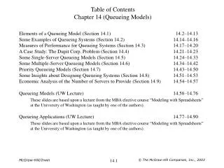
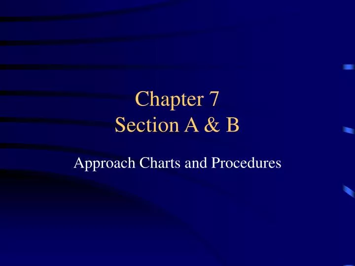
Chapter 7 Section A & B. Approach Charts and Procedures. Old Chart Format. New Chart Format. Instrument Approach Procedure. Precision Approach - ILS, PAR Lateral and Vertical navigation Nonprecision Approach - VOR, NDB, GPS Only Lateral navigation. Approach Segments. Feeder routes

E N D
Chapter 7Section A & B Approach Charts and Procedures
Instrument Approach Procedure • Precision Approach - ILS, PAR • Lateral and Vertical navigation • Nonprecision Approach - VOR, NDB, GPS • Only Lateral navigation
Approach Segments • Feeder routes • Approach transitions or Terminal routes • THESE ARE NOT PART OF THE ACTUAL PUBLISHED APPROACH!
Review Charts • Plan View • Profile View • TDZE • HAT - based on TDZE for straight in approaches • HAA - based on airport elevation for circling • TCH • Missed Approach • Minimums • Ground Speed and Time
Approach Categories • 1.3XVso • Baron Vso=75kts • 75 X 1.3=97.5 • VFR final approach speed short field is 90kts • IFR Approach speed is 120IAS (B) • Minimum IAS Icing conditions is 130IAS (C)
Initial Approach Segments • IAF - Must proceed here first (maybe radar vectors) • MVA - 1,000 or 2,000 obstructions clearance • also 300+ above floor of controlled airspace • maybe lower than the MEA or MOCA
Initial Approach Segments • Procedure turns or course reversals • May use a holding pattern in lieu of • Max speed is 200 kts IAS
Intermediate Approach Segment • IF - Intermediate Fix • Aligned with 30º of final approach course • Usually inbound to the final approach fix
Final Approach Segment • FAF • Nonprecision - maybe the VOR or NDB • Precision - is interception of the Glide Slope or Glide Path at a minimum intercept altitude • FAP • Nonprecision - when the VOR or NDB is on the field and you intercept the final approach course inbound (MPR)
Final Approach Segment • Timed approaches from a holding fix Radar service for sequencing traffic is out of service If you are told to depart the holding fix at a certain time, timed approaches are in progress! • Requirements • Control tower in operation • Direct communication to the approach controller • MAP do not require a course reversal and the weather is greater than the highest prescribed circling minimums for the IAP • When cleared for the IAP NOPT is available
Minimum Decent Requirments • DH or DA - Precision • Followed by Min. Visibility and HAT • MDA - Nonprecision • Followed by Min. Visibility and HAT or HAA
Final Approach • Operations below DH or MDA FAR 91.175 Please Read • Flight visibility not less than required • Aircraft must be continuously in a position to land using normal descents and maneuvers
Final Approach • One must be distinctly visible and identifiable • Threshold • Threshold markings • Threshold lights • Runway end identifier lights (REIL) • Visual approach slope indicator (VASI or PAPI) • Touchdown zone or touchdown zone markings • Touchdown zone lights • Runway or runway markings • Runway lights
Final Approach • Approach lighting system (ALSF, MALSR OR SALSR) • If only the approach lighting system is in sight you may descend down to 100ft above TDZE • If the red terminating bars (ALSF-1) or the red side row bars (ALSF-2) are in sight you may land
Landing Minimums • Visibility and Minimum Altitudes • Factors include • Approach lighting system • Obstructions • Equipment on board • Approach speed • Straight in or circling • Sidestep Maneuver
Stepdowns and VDP’s • Stepdown at different approach segments • Only one between FAF and MAP • VDP - Must not leave your MDA before this point!
Missed Approach Segment • MAP • DH, VOR, NDB, Time (Based on GS), DME fix • During radar approaches ATC will give you the MAP
Minimum Sector Altitude • Minimum safe altitude • Within 25 of a FIX allows 1,000 of obstruction clearance
Inoperative Components An increase in minimum visibility requirements due to inoperative approach lighting systems. Different types of approaches, different changes Refer to the inop. component chart
Additional Information • ARP - Airport Reference Point - The approximate geometric center of all usable runway surfaces • Details about taxi ways and runway lengths
Take-Off Minimums • Part 91, Zero-Zero • Rule of thumb, be able to get back into the airport your took off from. • Non-Standard Take-Off Minimums • Weather or IFR Departure Procedure
Alternate Required? • Always • Unless you meet the 123 Rule! • One hour before or after your ETA to destination if weather is greater than a 2000 ft ceiling or 3 statue miles of visibility. • This is voided if your destination airport doesn’t have a IAP.
Now we need and Alternate • Standard • Precision - 600-2 • Nonprecision - 800-2 • Nonstandard alternate minimums
Types of Approaches • Visual approach (Field must be VFR) • Contact approach (Pilot must request) • IAP • Precision • Nonprecision