Download
1 / 39
390 likes | 520 Views
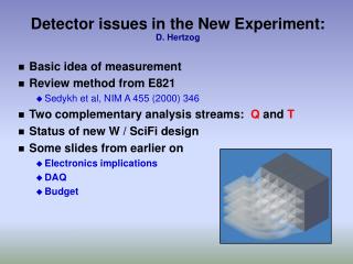
Detector Issues. H. Wieman Feb. 7, 2002 STAR Collaboration Meeting. Outline. Detectors under consideration BNL Detector R&D Workshop Nov. 01 Some detector decisions TPC replacement? Option for increased capability Are there fundamental limits at 40X luminosity upgrade Progress

E N D
Detector Issues H. Wieman Feb. 7, 2002 STAR Collaboration Meeting
Outline • Detectors under consideration • BNL Detector R&D Workshop Nov. 01 • Some detector decisions • TPC replacement? • Option for increased capability • Are there fundamental limits at 40X luminosity upgrade • Progress • Tests of micro pattern gas detectors • Active Pixel Sensor (APS) development
Upgrade considerations • Build large TOF barrel (RPC ALICE/STAR R&D) • Install high precision inner vertex detector • Extend high quality forward tracking
Upgrade considerations • Forward RICH, Yale • TPC replacement plus RICH - Nikolai Smirnoff • High speed FEE/RDO for current TPC
RHIC Detector WorkshopNov 13-14, 2001 Semiconductor Vertex Tracking Rene Bellwied, Wayne State U. Gas Tracking Detectors Itzhak Tserruya, Weitzmann Inst. Particle Identification Hideki Hamagaki, Univ. Tokyo Trigger/Data Acquisition James Nagle, Columbia U.
Detector Decisions • Present TPC vs Replacement • Can the present TPC work with the X40 luminosity upgrade • If TPC is replaced what are the trade offs, what are the physics benefits
Can the present TPC handle X40 luminosity upgrade • Space charge induced drift distortion? • Observed DCA = 2.7 mm from Space Charge (Jamie Dunlop showed dependence on CTB scaler rate) • Space Charge depends on beam current not interaction rate (charge comes from upstream background) • Expect 12 mm with full 110 bunches x 109 ions • Jamie can correct 2.7 mm to 250 microns • DCA RMS does not increase with scaler rate • Conclusion: Distortion Problem is probably not a show stopper
Can the present TPC handle X40 luminosity upgrade • Wire aging? • Depends on track multiplicity and gate open rate • This depends more on FEE/RDO rates than luminosity • 2kHz of central collisions – 4 years to reach limit of 0.1 Coul/cm on inner wires • Conclusion: Wire aging probably not a show stopper • Tracking problems from pileup?
Present TPC vs replacement • Conclusion: Luminosity upgrade does not force a decision • Remains a question of physics priorities • Additional room for detectors with improved particle ID vs expense and energy • What improvements are possible using present TPC with new high rate FEE/RDO/DAQ and increased trigger capability?
Replacement TPC, Technical issues • Is pure silicon better – probably too expensive and gives poorer low momentum resolution • The outer pad chambers – how many needed for adequate tracking and how expensive • Drift gas CF4 vs CH4 • Micro pattern readout – robustness with heavily ionizing tracks • Development needs and an early R&D progress report next>>
Experimental set-up I.Giomataris,G.Smith,B.Yu Micro-pattern gas chamber readout for TPC
Micro-photograph of Micromegas I.Giomataris,G.Smith,B.Yu 5 m copper, 25 m diameter holes, 50 m pitch 50 m tall Kapton pillar Pillar spacing normally 1mm ( 2mm on test sample) 50 m
Anode plane: Al strips with pitch 0.95 mm I.Giomataris,G.Smith,B.Yu Center 12 strips bussed together, to preamplifier. Load 150 pF. Rest of strips grounded for present measurements. 152 mm Active area of micromegas mesh Section used for measurements (12 mm wide by 70mm) 152 mm
Measurement instrumentation I.Giomataris,G.Smith,B.Yu Collimator (25 m, 100 m, 1 mm) Monochromator Energized X-ray source Detector
Charge and Gain vs HT I.Giomataris,G.Smith,B.Yu
+ve ion transmission I.Giomataris,G.Smith,B.Yu Must check if this is an issue for a small TPC
Comments I.Giomataris,G.Smith,B.Yu • Micromegas mesh tested in Ar/20%CO2 and pure CF4 • Gas gain ~ 7,000 achieved in Ar/20%CO2 and ~ 300 in CF4 • 2mm post spacing may limit upper voltage, and hence gain, with CF4 • Resn of 16% and 27% FWHM in Ar/20%CO2 and pure CF4 at 5.4 keV • Positive ion feedthrough ~ 1% with ED = 200 V cm-1 • Collimated beam cyclic gain change (~ 3%) across mesh holes • Tests continue: Ar/10%CH4, Ar/20%DME, ~ 10ns shaping, ion drift velocity, local gain variation, lateral diffusion….
GEM Detector Courtesy of F. Sauli (CERN) N. Smirnov/ C. Woody Additional GEM foils will be used to construct readout detector for TPC Drift Cell
GEM TPC F.Sauli (CERN) Narrow pad response function (Ds ~ 1 mm): Improved multi-track resolution Fast signals (no ion tail) DT~20 ns : F Intrinsic multi-track resolution DV ~ 1 mm3 (Standard MWPC TPC ~ 1 cm3) N. Smirnov/ C. Woody
TPC Readout Plane and Electonics P.O’Connor & Bo Yu (BNL) Readout Pads DR ~ 1 cm f ~ 2 mm Segmentation driven largely by resolution
VUV Spectrometer Measures optical transmission down to 120 nm Bob Azmoun and Craig Woody
TOF Barrel • RPC plate technology (50 ps), different then current installed systems that have problems • Rice/ALICE • Bill Llope, Jose Lamas-Velverde (thesis), Geary Eppley • ALICE • Beam testing at BNL • Test slat in STAR • Outstanding issues – a TDC?
Strawman / Potential layouts • Strawman technology = Silicon Strip • double-sided Silicon Strip detector, 100 micron pitch • 5 by 5 cm active area, 1000 channels/wafer • 300+320 wafers (see layout below) • 0.8 and 0.75 m2 of active Silicon, respectively • potential location:in front of FTPC • 5 layers (z=60,80,100,120,140 cm ; r=10,15,20,25,30 cm) • h = 2.3-4.0 (320,000 channels) • potential location: behind FTPC • 5 layers (z=350,375,400,425,450 cm ; r=20 cm all planes) • h = 3.5-5.0 (300,000 channels) Bellwied, November 2000
Potential Layouts • two ‘stations’ in front and behind the FTPC • develop a quasi-circle • use single-sided Si • have FEE on disk edges • use TAB Technology ? Bellwied, June 2001
RICH Detectors • Continuation of STAR RICH program • Located forward or • If TPC removed then in the cylinder • Gerd Kunde, Nikolai Smirnoff, Jamie Dunlop, Brian Lasiuk of Yale • Possible Yale development of CsI photo cathode production
RICH Development, Yale • Investigation of CVD Diamond replacement for Cs-I by Brian Lasiuk Hamamatsu R7639
Faster TPC readout • Tonko next talk • Interest by Tonko, Fred and Hank • Low impact solution to high luminosity operation
Active Pixel Sensor (APS) • 20 m square pixels • 5 chips per slat • 90 million pixels • 40 m thick chips 5.6 cm 8 cm
B A e- A-A’ B-B’ B’ A’ MEMOSA APS A Monolithic Active Pixel Sensor for Charged Particle Tracking and Imaging using Standard VLSI CMOS TechnologyJ.D. Berst, B. Casadei, G.Claus, C.Colledani, W.Dulinski, Y.Hu, D.Husson, J.P.Le Normand, R.Turchetta and J.L.RiesterLEPSI, IN2P3/ULP, Strasbourg, FranceG.Deptuch1, S.Higueret, M.WinterIReS, IN2P3/ULP, Strasbourg, France1vistitor from UMM, Cracow, Poland
128X128 pixels 0.25 m CMOS TSMC through MOSIS 4 styles row selection shift register column selection shift register n well collection nodes First chip – tested and works S. Kleinfelder
SK chip design Cg • 4 pixel styles • Added FET acts as • Sample and hold (off or on) or • Capacitance isolator (TX held constant at intermediate voltage) Vsg Cd capacitance isolator Cg Cd Vsg drops to Vthreshold and any additional charge spills to drain (Cg). Only Cg is reset Copy of MIMOSA style
LBL APS test with 1.5 GeV/c e-beam 17 e RMS per pixel
LBL APS measured MIP signal Sums of 25 pixel regions centered on pixels with ADC 7 Same sums with empty frames Background subtracted APS signal with Bichsel calculation for 8 mm Si • Conclusion, signal to noise is good enough to get good efficiency without excessive false hits • The above analysis is with CDS and leakage current subtraction
Summary • Present TPC will probably handle luminosity with new electronics • Forward tracking and inner vertex improve physics reach without disruption • Improved particle ID possible at mid rapidity with RICH, Aero gel etc. - but must replace TPC to free up real estate
Leakage Current • Mean pixel current 0.9 fA or 5600 e/sec • Q leakage = 1 MIP in 70 ms • Negligible with cooling (preliminary), i.e. won’t need correction for zero suppress
0 0 0 0 0 0 4 4 4 4 4 4 8 8 8 8 8 8 Pion-Kaon separation Kaon-Protonseparation TOF s~100 ps 0 - 2.5 0 - 5 RICH n=1.004 5 - 17 17 - Aerogel n=1.007 1 - 5 5 - 9 Extended PID with Aerogel Y. Miake Aerogel together with TOF can extend the PID capability up to ~ 10 GeV/c