Download
1 / 36
360 likes | 785 Views
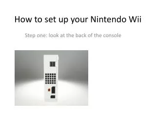
Nintendo Wii Sensor Bar Replacement. Group 9 Jacob Huh, Scott Kammlade, and Nathaniel Toca April 25, 2008. Wii Sensor Bar. Infrared (IR) light source Controller contains IR sensor Sensor detects controller position relative to IR light source. Sensor Bar Replacement.

E N D
Nintendo Wii Sensor Bar Replacement Group 9 Jacob Huh, Scott Kammlade, and Nathaniel Toca April 25, 2008
Wii Sensor Bar • Infrared (IR) light source • Controller contains IR sensor • Sensor detects controller position relative to IR light source
Sensor Bar Replacement • Mobile IR light source • Controlled through eye movements • Reduces space and movement required for play • Adjustable for each user
EOG Theory • Front of the retina is electropositive with respect to the back of the retina • Electrodes can detect differential voltage • Electrode becomes more positive as eye moves toward it • i.e. - electrodes above and below the eye determine the vertical direction of gaze
Electrode Placement • Horizontal: A and B • Vertical: C and D • Reference: E
EOG Circuit • Four main component: • Stage 1&3: amplification • Stage 2&4: high & low-pass filter
Previous EOG Circuits • Spring 1999: Alex Chu, Everest Chiu
Comparison • Main difference: LM741 to AD622 chip • Benefits of using AD622: 1) Gain set with single resistor 2) Excellent noise rejection 3) Can control Voffset • AD622 well-suited for calibration
LED Matrix Aspect ratio TV aspect ratios – 4:3 and 16:9 Need more horizontal resolution than vertical 10:8 is a practical compromise Distance from remote Ideally – very close Reality – being too close results in frequently “lost” cursor Tradeoff in selectable screen area
LED Matrix • X-Y addressing • LED’s respond to voltage difference • Column selected with low voltage (desired column = low, all others = high) • Row selected with high voltage (desired row = high, all others = low) • Current limiting • 1k Resistors at row inputs • For V = 5V, I = 5mA
EOG Stage 1: Pre-amplification • Trace 1: Input • 106 mVpp • Trace 2: Output • 9.19 Vpp • Gain: 9.19V/106 mV = 86.7
EOG Stage 2: High Pass Filter • -3dB Freq: • Vout = 0.71Vin • Trace 1: Input • Trace 2: Output • -3dB Freq: 0.155 Hz
EOG Stage 3: Amplification • Trace 1: Input • 56 mVpp • Trace 2: Output • 103 mVpp • Min Gain: 1.87 • Max Gain:~ 1000
EOG Stage 4: Low Pass Filter • Trace 1: Input • Trace 2: Output • -3dB Freq: 29.94 Hz
EOG Common Mode Rejection Ratio • CMRR measures ability to reject noise present on both inputs • Difficult to measure – various techniques • Ratio of common mode input voltage and differential input voltage for which output is the same • CMRR = 20 log (Vc / Vd) • Previous EOG groups used different measurement technique
EOG Common Mode Rejection Ratio • Vc = 3.643 V • Vd = 0.48 mV • CMRR = 20 log (3.643 / 0.00048) = 77.6 dB
EOG Calibration Out In Vertical Horizontal
EOG Signal-to-Noise Ratio • Signal ~ 5V • Noise ~ 0.08V • SNR ~ 62.5 • Limiting factor in size of LED array
Microcontroller Testing • 0-5 Vpp signal input to microcontroller • Output of each pin observed • Trace 1: Input Signal • Trace 2: Pin Output 1 2 2 1
Response Time • Trace 1: Input to EOG • Trace 2: LED signal • Response time faster than the 60Hz at which televisions operate 2 1
LED Matrix Testing • Cannot visually verify which LED is lit • Connectivity tests using DMM • 8x8 visible LED matrix purchased for LED addressing tests
Operation with Wii • Strengths • Very intuitive • Fast response • Well-suited for menu navigation • Weaknesses • Limited resolution • Limited downward movement • Difficult to calibrate
Opportunities • Automatic calibration • Get rid of electrodes • Larger and denser LED array • Transition to monolithic LED matrix is ideal • Noise reduction • Integration with Wii controller
Marketability • Cost • Component Costs • IR LEDs - $0.40 each • ICs ~ $15 total • Replacement Electrodes • Safety Issues • Macroshock • Current-limiting resistors
Credits • Dr. Kenneth Gentry • Mr. Tomasz Wojtaszek • Mr. Mark Smart