Download
1 / 31
330 likes | 825 Views
Objectives. Discuss the basic op-ampExplain the basic operation of a differential amplifierDiscuss several op-amp parametersExplain negative feedback in op-amp circuitsAnalyze three op-amp configurationsDescribe the effects of negative feedback on the three basic op-amp configurations. Introduc

E N D
1. Chapter 18 Operational Amplifiers (Op-Amps)
2. Objectives Discuss the basic op-amp
Explain the basic operation of a differential amplifier
Discuss several op-amp parameters
Explain negative feedback in op-amp circuits
Analyze three op-amp configurations
Describe the effects of negative feedback on the three basic op-amp configurations
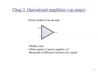
3. Introduction to Operational Amplifiers The standard Operational amplifier has two input terminals, the inverting (-) and noninverting (+)
4. Introduction to Operational Amplifiers The ideal op-amp has:
infinite voltage gain
an infinite input impedance (open)
does not load the driving source
zero output impedance
The practical op-amp has:
high voltage gain
high input impedance
low output impedance
5. The Differential Amplifier A basic differential amplifier is shown below
There are two outputs, where the op-amp has one
It requires a negative and positive supply voltage
6. The Differential Amplifier When a diff-amp is operated in single-ended input mode, one input is grounded and the signal voltage is applied only to the other input
In differential mode, two signals of opposite polarity (out-of-phase) are applied to the inputs
also referred to as double-ended
Common-mode Input is the condition where two signal voltages of the same phase, frequency and amplitude are applied to the two inputs
7. The Differential Amplifier Common-mode rejection describes the result when input signals are applied to both inputs, the outputs are superimposed and they cancel, resulting in near zero output voltage
Common-mode rejection ratio (CMRR) is a measure of an amplifiers ability to reject common-mode signals
practical amplifiers exhibit a very small common-mode gain (usually much less than 1)
8. The Differential Amplifier A typical op-amp is made up of three types of amplifier circuits:
Differential amplifier
Input stage for the op-amp; it has two inputs and provides amplification of the difference voltage
Voltage amplifier
Usually a class A amplifier that provides gain
Push-pull amplifier
Class B amplifier is used for the output stage
9. Op-amp Parameters Input Offset Voltage VOS
Input offset voltage is due to a slight mismatch of the base-emitter voltages of the differential input stage
It is the differential dc voltage required between the inputs to force the differential output to zero volts
Input Offset Voltage Drift with Temperature
Input offset voltage drift with temperature is a parameter that specifies how much change occurs in the input offset voltage for each degree change in temperature (typical values range from 5 ?V to 50 ?V per degree Celsius)
10. Op-amp Parameters Input Bias Current
Input bias current is the direct current required by the the inputs of the amplifier to properly operate the first stage; by definition, it is the average of both input currents
IBIAS = (I1 + I2)/2
Input Impedance
Differential input impedance is the total resistance between the inverting and noninverting inputs; it is measured by determining the change in bias current for a given change in differential input voltage
11. Op-amp Parameters Common-mode input impedance is the resistance between each input and ground and is measured by determining the change in bias current for a given change in common-mode input voltage
Input Offset Current
Input offset current is the difference of the input bias currents, expressed as an absolute value
IOS = |I1 - I2|
Actual magnitude of offset current is usually at least an order of magnitude less than the bias current
12. Op-amp Parameters Output Impedance
Output impedance is the resistance viewed from the output terminal of the op-amp
Common-Mode Input Voltage Range
Common-mode input voltage range is the range of input voltages which, when applied to both inputs, will not cause clipping or other output distortion
Typically � 10 V with dc supply voltages of � 15 V
13. Op-amp Parameters Open-Loop Voltage Gain, Aol
Open-loop voltage gain of the op-amp is the internal voltage gain of the device and represents the ratio of output voltage to input voltage when there are no external components (set entirely by internal design)
Open-loop voltage gain can range to 200,000 or more
Common-Mode Rejection Ratio
Common-mode rejection ratio (CMRR) is a measure of an op-amp�s ability to reject common-mode signals
CMRR = Aol / Acm
14. Op-amp Parameters Slew Rate
Slew rate of an op-amp is the maximum rate of change of the output voltage in response to a step input voltage
Slew rate is dependent upon the frequency response of the amplifier stages within the op-amp
Slew rate = ?Vout / ?t
Frequency Response
Frequency response of an op-amp has voltage gains limited by junction capacitances
Low frequency response of an op-amp extends down to dc, since there are no internal coupling capacitors
15. Op-amp Parameters
16. Negative Feedback The inverting input (-) effectively makes the feedback signal 180� out of phase with the input signal
When negative feedback is present, the noninverting and inverting inputs are nearly identical
17. Negative Feedback Since the inherent open-loop gain of a typical op-amp is very high, usually > 100,000, an extremely small difference in the two input voltages drives the op-amp into its saturated output states
The usefulness of an op-amp operated in this manner is severely restricted and is generally limited to comparator applications
With negative feedback, the overall closed-loop gain (Acl) can be reduce and controlled so that the op-amp can function as a linear amplifier
18. Op-amp Configurations with Negative Feedback Closed-loop voltage gain
Closed-loop voltage gain is the voltage gain of an op-amp with negative feedback
An external feedback network connects the output to the inverting input
The closed-loop voltage gain is determined by the component values in the feedback network
19. Op-amp Configurations with Negative Feedback An op-amp connected as a noninverting amplifier has the input signal applied to the noninverting input, and a portion of the output applied back to the inverting input through the feedback network
20. Op-amp Configurations with Negative Feedback The feedback fraction, B, is determined by the feedback network as:
B = Ri / (Ri + Rf)
The closed-loop voltage gain Acl(NI) of the noninverting (NI) amplifier is not dependent on the op-amp�s open-loop gain but can be set by selecting values of Ri and Rf
Acl(NI) = (Rf / Ri) + 1
21. Op-amp Configurations with Negative Feedback The voltage-follower is a special non-inverting amplifier were all of the output voltage is fed back to the inverting input
very high input impedance
very low output impedance
22. Op-AMP Configurations with Negative Feedback An op-amp connected as an inverting amplifier
Closed-loop gain is:
Acl(I) = - Rf / Ri
Closed-loop gain is independent of the op-amp�s internal open-loop gain
23. Op-amp Impedances Noninverting op-amp impedances
Input impedance of a noninverting amplifier is greater than the internal input impedance of the op-amp itself (without feedback)
Zin(IN) = (1 + AolB)Zin
Output impedance with the negative feedback is less than the op-amp output impedance
Zout(NI) = Zout / (1 + AolB)
24. Op-amp Impedances Voltage-follower impedances
Input impedance is greater than for the noninverting configuration with the voltage-divider feedback circuit
Zin(VF) = (1 + Aol)Zin
Output impedance is much smaller than for a noninverting configuration
Zout(VF) = Zout / (1 + Aol)
25. Op-amp Impedances Inverting op-amp impedances
Input impedance approximately equals the external input resistance because of the virtual ground at the inverting input
Zin(I) ? Ri
Output impedance approximately equals the internal output impedance of the op-amp
Zout(I) ? Rout
26. Summary The op-amp has three terminals, not including power and ground: inverting (-), noninverting (+), and output
Most op-amps require both a positive and a negative dc supply voltage
The ideal op-amp has infinite input impedance, zero output impedance, infinite open-loop voltage gain and infinite CMRR
27. Summary A good practical op-amp has high input impedance, low output impedance, and high open-loop voltage gain
A diff-amp is normally used for the input stage of an op-amp
A differential input voltage appears between the inverting and noninverting inputs of a diff-amp
A single-ended input voltage appears between one input and ground (with the other inputs grounded)
28. Summary A differential output voltage appears between two output terminals of a diff-amp
A single-ended output voltage appears between the output and ground of a diff-amp
Common mode occurs when equal, in-phase voltages are applied to both input terminal
Input offset voltage produces an output error voltage (with no input voltage)
29. Summary Input bias current also produces an output error voltage (with no input voltage)
Input offset current is the difference between the two bias currents
Open-loop voltage gain is the gain of the op-amp with no external feedback connections
Slew rate is the rate (in volts per microsecond) that the output voltage of an op-amp can change in response to a step input
30. Summary Negative feedback occurs when a portion of the output voltage is connected back to the inverting input such that it subtracts from the input voltage, thus reducing the voltage gain but increasing the stability and bandwidth
There are three basic op-amp configurations: inverting, noninverting, and voltage-follower
All op-amp configurations (except comparators, covered in the next chapter) employ negative feedback
31. Summary A noninverting amplifier configuration has a higher input impedance and a lower output impedance than the op-amp itself
An inverting amplifier configuration has an input impedance approximately equal to the input resistor Ri and an output impedance approximately equal to the internal output impedance of the op-amp itself
The voltage-follower has the highest input impedance and the lowest output impedance of the three configurations