Download
1 / 30
300 likes | 465 Views
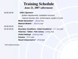
Training Schedule June 22, 2007 (afternoon). 02:00-03:30 Model Generation* - Fitting the 3DEC model to a problem region - Joint generation Material Models* - Joint models - Deformable-block material models 03:30-03:45 Break

E N D
Training ScheduleJune 22, 2007 (afternoon) 02:00-03:30 Model Generation* - Fitting the 3DEC model to a problem region - Joint generation Material Models* - Joint models - Deformable-block material models 03:30-03:45 Break 03:45-05:30 Boundary Conditions / Initial Conditions* - Applying boundary conditions - Initializing variables Solution - Solving for force equilibrium - Cycling to monitor material failure Result Interpretation* Practical Exercise - Stability analysis of an underground excavation * with simple exercises
Available Memory Dictates Number of 3DEC Blocks * 24 translation degrees of freedom are assumed for blocks
Model Building in 3DEC Two approaches: • Cut up a large polygon into the desired geometry • Create separate polyhedra and connect them together
Model generation commands to create and shape a large polyhedron POLY brick xl,xu yl,yu zl,zu POLY facexa1,ya1,za1 xa2,ya2,za2 ... face xb1,yb1,zb1 xb2,yb2,zb2 ... . . POLY prism axa1,ya1,za1 xa2,ya2,za2 ... bxb1,yb1,zb1 xb2,yb2,zb2 ... POLY tunnel keywords ...
Model generation commands to cut up a large polyhedron JSET keywords ... TUNNEL region n ... POLY cube
POLY face &POLY brick poly & face 0,0,0 1,0,0 1,1,0 0,1,0 & face 0,0,0 0,0,1 1,0,1 1,0,0 & face 0,0,0 0,1,0 0,1,1 0,0,1 & face 1,1,1 1,1,0 1,0,0 1,0,1 & face 1,1,1 1,0,1 0,0,1 0,1,1 & face 1,1,1 0,1,1 0,1,0 1,1,0 poly brick 0,1 0,1 0,1
POLY prism poly prism a (0,0,0) (-.5,.87,0) (-.5,1.87,0) (0,2.74,0) & (1,2.74,0) (1.5,1.87,0) (1.5,.87,0) (1,0,0) & b (0,0,4) (-.5,.87,4) (-.5,1.87,4) (0,2.74,4) & (1,2.74,4) (1.5,1.87,4) (1.5,.87,4) (1,0,4)
POLY tunnel poly tunnel rad=2 leng=-10,10 ratr=3.0 dip=0 dd=0 nr=2 nt=1 nx=3 delete -2 2, -10 10 -2 2 join on join on
Fracture/joint representation in 3DEC • Fractures are represented by cuts in blocks • Cuts must “knife” completely through a particular block • Blocks can be hidden to avoid cutting • Blocks can be joined at common faces to form concave blocks • Fracture termination within block is accounted for by either: • adjusting rock stiffness • using high strength for non-fracture portion of cut
Joint generation commands JSET dipv1 ddv2 originx y z persistencep numn spacings id i HIDE/SEEK JOIN on/off
Definition of joint orientation • 3DEC 4.0 uses left-handed (CONFIG lhs) or right-handed (CONFIG rhs) coordinate systems (by default, right-handed) • JSET creates single or multiple cuts • HIDE and SEEK control continuity of cuts right-handed system
JSET poly brick 0,1 0,1 0,1 ; create a block jset dip 0 dd 0 or 0,.5,0 ; make a horizontal cut hide dip 0 dd 0 or 0,.5,0 below ; hide the bottom block jset dip 90 dd 90 or .5,0,0 ; vertical cut through top block only seek ; make all blocks visible
JSET poly brick 0 80 -30 80 0 50 ; shallow-dipping fracture planes (continuous) jset dip 2.45 dd 235 org 30 0 12.5 jset dip 2.45 dd 315 org 35 0 30 ; high angle foliation planes (continuous) jset dip 76 dd 270 spac 16 num 3 org 30,0,12.5 ; intersecting discontinuities (non-continuous) hide range x 0,80 y 0,50 z 0,10 hide range x 55,80 y 0,50 z 0,50 jset dip 70 dd 200 org 0 35 0 jset dip 60 dd 330 org 50 15 50 seek hide range x 0,30 y -30,80 z 13,50
TUNNEL config lh poly brick -1.5,1.5 -1.5,1.5 -1.5,1.5 tunnel radial region 1 & a (-0.30,0.00,-1.5) (-0.3,0.40,-1.5) (-0.25,0.47,-1.5) & (-0.15,0.52,-1.5) ( 0.0,0.55,-1.5) ( 0.15,0.52,-1.5) & ( 0.25,0.47,-1.5) ( 0.3,0.40,-1.5) ( 0.30,0.00,-1.5) & b (-0.30,0.00, 1.5) (-0.3,0.40, 1.5) (-0.25,0.47, 1.5) & (-0.15,0.52, 1.5) ( 0.0,0.55, 1.5) ( 0.15,0.52, 1.5) & ( 0.25,0.47, 1.5) ( 0.3,0.40, 1.5) ( 0.30,0.00, 1.5) remove region 1
Model set-up guidelines • Orient 3DEC model axes in a such way to reduce coordinate transformations (for model geometry and for geological features) – e.g. use mine grid or align model axes to centerline of a tunnel. • Do not use coordinates with more than 5 digits if you use the single-precision version of 3DEC. • It is impossible and unnecessary to include all discontinuities in the model: include the most critical joints that will affect mechanical response of the model. • Start with the simplest possible model (no joints in the model or all joints glued). Then try to calibrate model with observations; if agreement is achieved joints are not needed, otherwise include joints
Zoning of deformable blocks • selection of rigid or deformable blocks • automatic zone generation using • tetrahedral zones (GEN edge), or • “quad” zoning (mixed discretization) of six-sided polyhedra (GEN quad) GENedge l GENquad ndiv i1 i2 i3
Zoning of deformable blocks • nodal mixed discretization • tetrahedral zones (GEN edge and SET nodal on) • nodal mixed discretization improves accuracy for plasticity analysis using tetrahedral zones GENedge 0.5 SET nodal on
Extended Constitutive Models for Deformable Blocks CONFIG cppudm ZONE load {filename} ZONE model {model name} hoek vchoek.dll Hoek-Brown model
Material properties • Definition of material types PROPERTY matim bulkv ... PROPERTY jmatjm kn v ... • Assignment of the material numbers to different parts of the model CHANGE matim CHANGE jmatjm
Types of boundaries • Real boundaries, e.g., • ground surface, • boundary of mined area • Artificial boundaries, e.g., • symmetry planes • caution: if discontinuities are present in the model symmetry usually cannot be used • boundary truncation – far field boundaries • possible analysis on different scales and transfer of stresses from the large scale model to the small scale model as boundary conditions
Stress boundary conditions (1) BOUNDARY stresssxxo syyo szzo sxyo sxzo syzo xgrad sxxx syyx szzx sxyx sxzx syzx ygrad sxxy syyy szzy sxyy sxzy syzy zgrad sxxz syyz szzz sxyz sxzz syzz
Stress boundary conditions (2) • Note that sxxo syyo szzo sxyo sxzo syzo are stresses at the origin of the 3DEC model, while stress boundary conditions are usually given with respect to ground surface • Stress boundary conditions can be varied as a function of time using keyword history • If new stress boundary condition is applied it is superposed to the existing stress boundary condition • Check boundary conditions before running the modelwithPRINT bound
Displacement boundary condition • Displacements are controlled indirectly through velocity boundary conditions • For deformable blocks BOUNDARY xvelx yvely zvelz • For rigid blocks APPLY xvelx yvely zvelz • to fix velocity FIX
Initial conditions INSITU stresssxxo syyo szzo sxyo sxzo syzo xgrad sxxx syyx szzx sxyx sxzx syzx ygrad sxxy syyy szzy sxyy sxzy syzy zgrad sxxz syyz szzz sxyz sxzz syzz
Suggestions for model checking (1) • Check that material and constitutive model numbers have been assigned to the desired blocks. Try the following. HIDE to hide all but last block PRINT block to find material number of last block SEEK materialn to seek blocks of material number n PLOT block to view these blocks • Check to see if joint material numbers have been assigned to desired joints. Try the following. PRINT cp to find material number of contacts between blocks
Suggestions for model checking (2) • Pay close attention to joint material numbers assigned to edge-to-edge or face-to-edge contacts. This is important when assigning joint material numbers using Change dip=xxdd=yyjmaterial=n • Check geometry of zones for required level of detail. This is critical for areas of interest where special behavior (i.e., large deformations) may be expected. • Check boundary conditions by using PRINT boundary state • Check joined blocks by either printing contact data between blocks or checking master/slave conditions by typing PRINT lg This will give a list of blocks that are joined together.
Suggestions for model checking (3) • Check assigned regions by hiding and seeking blocks by region and then plotting those blocks. This can also be done by getting block attributes in screen mode. • Check magnitude of properties using the following: PRINT property blocks for rock mass PRINT property joints for joints • Check assigned locations of history points by listing history points HISTORY list • Check initial stresses to ensure that correct gradients have been applied and magnitudes are correct.
Practical Exercise: Stability Analysis of an Underground Excavation joint plane 3 joint plane 1 jointed rock unit weight 20,000 N/m3 bulk modulus 1.5 GPa shear modulus 0.6 GPa three joint planes: 1. dip angle 65o dip direction 270o origin 0.3,0.0,0.0 2. dip angle 40o dip direction 230o origin 0.0,-0.3,0.0 3. dip angle 50o dip direction 320o origin 0.0,0.0,0.3 joint normal & shear stiffness 1.0 GPa/m joint cohesion 0 joint friction angle 6o joint plane 2 run 3DEC