Download
1 / 10
100 likes | 241 Views
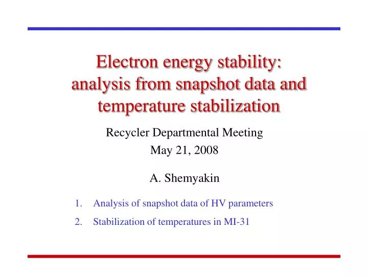
Electron energy stability: analysis from snapshot data and temperature stabilization. Recycler Departmental Meeting May 21, 2008 A. Shemyakin. Analysis of snapshot data of HV parameters Stabilization of temperatures in MI-31. Snapshot of HV – related parameters.

E N D
Electron energy stability:analysis from snapshot data and temperature stabilization Recycler Departmental Meeting May 21, 2008 A. Shemyakin Analysis of snapshot data of HV parameters Stabilization of temperatures in MI-31
Snapshot of HV – related parameters • All ECool BPMs are snapshotable • 700 Hz, 2048 points (~3 sec) • Greg’s HV diagnostics connected to IRM is snapshotable as well • 1 kHz, 2048 points (2 sec) • On the plot, all 4 sec is recorded • At standard conditions, the chain current signal is saturated, and for this snapshot the chain current was increased by 4 A 1sec 2 A Snapshot of the chain current fluctuations (red, 2 microA/div), error signal (blue, 2 microA/div), high-dispersion BPM BYR01Y (green, 1 mm/div), and AC component of HV (> 0.1 Hz, yellow, 1 kV/div). May 5, 2008
Terminal Potential Stabilizer (TPS) HV set point CPO Terminal Cp=300pF Quiescent needle current Chain current Error signal Terminal electronics Needle current Resistive divider Rp = 45 GOhm HV regulation schematic Generation voltmeter (GVM) and its preamplifier • Based on • GVM readback (R:GVMVLT), • HV set point (R:TPSTRV), • the set quiescent needle current (R:TPSPRQ), and • the gain (R:CTLGAN), • TPS produces the error signal (R:TPSERI, in A) • When the terminal electronics works correctly, the needle current follows R:TPSTRI • At constant beam loss and corona currents, the needle current varies only to compensate variations of the chain current
Chain current and Error signal • Amplitudes of FFT components of the chain current (red) and error signal (blue) in two frequency scales (in Hz) • No peaks above 60 Hz • Chain revolution frequency is 1.8 Hz • Chain motor frequency is 19.3 Hz • The regulation system’s bandwidth drops fast above several Hz • Origin of peaks at 12 Hz and 60 Hz in the error signal spectrum is unclear
Chain current and Error signal (cont.) FFT amplitudes of the chain current (red) and of the difference between the chain current and the error signal (blue) • The HV regulation system • suppresses 1.8 Hz component by a factor of ~3 • Amplifies 3.5 Hz line by a factor of ~2 • Doesn’t affect 5.5 Hz
Effect on HV FFT amplitudes of the electron energy derived from the high-dispersion BPM (red), from HV fluctuations measured by capacitive pickup (blue), and calculated from the balance of currents (green). • Assuming that the only reason for HV fluctuations is the misbalance Ibetween the chain and needle currents, one can calculate HV and compare FFT amplitudes with energy measurements • Effect of current fluctuations is dramatically suppressed at higher frequencies by the large terminal capacitance • Result of calculation is in a reasonable agreement with energy measurements In f > 1 Hz range, the electron energy ripple is ~0.15 keV rms. The major contribution comes from 1.8 Hz and 3.5 Hz lines.
Air conditioning of MI-31 • MI-31 temperature fluctuation • West wall unit was dying • Couldn’t work continuously • Repaired on May 12 • The control units measure the wall temperatures that are different from the average air temperature • West AC unit was blowing to its controller • In sunny days, walls may be hotter than air • Kermit moved West unit sensor to the tank • West unit was blowing directly on the GVM preamplifier • Preamp temperature was fluctuating by ~5C • Kermit isolated preamp • Change units’ settings • West unit works continuously in a steady state • North and East units regulate GVM preamplifier and R:TNKT1 N W Pelltron tank R:MI31T1 thermocouple E
Dependence of electron energy on the air temperature • a GVM SF6 temperature Energy deviation MI-31 temperature 2 keV 6hr T1 temperature Controlled access to put the GVM preamplifier and T1 thermocouple into a box 2 C Behavior of energy deviation before and after Kermit put the GVM preamplifier and T1 thermocouple into an thermally insulated box. In steady state, the main component of energy oscillations is caused by changes of the GVM preamplifier temperature.
Present status After the changes, “fast” (~1 hr) energy oscillations disappeared. Longer-term drifts seem to decrease only slightly, but there were no large (> 1 keV) deviations. Kermit thinks about a thermal stabilization of the preamp temperature, but it will be difficult to judge about changes until NMRs are repaired. 1day SF6 temperature MI-31 temperature T1 temperature Energy deviation 1 keV 1 C 0.5C 1 C
Summary • Energy ripple above 1 Hz is ~0.15 keV rms and is determined by fluctuations of the chain current and by imperfection of the HV regulation system • Energy ripple at > 5 Hz is suppressed by the large Pelletron tank capacitance • Presently the electron energy drift is caused primarily by temperature fluctuations of the GVM preamplifier • 1-hr range oscillations disappeared after thermal insulation of the preamp • The drift is within 0.5 keV • After changes and repairs of air conditioning, MI-31 temperature stays within 1 C • At least, in these cloudy days • No dramatic (> 1 keV) energy drifts is observed recently • To trace efficiency of next improvements (like thermal stabilization of GVM preamplifier), 180-deg bend NMRs needs to be repaired.