Download
1 / 19
190 likes | 326 Views
ATF2 optics, tuning method and tolerances of initial alignment, magnets, power supplies etc. Andrei Seryi for the ATF2 optics design team. Optics Design of ATF2. ATF2 design & goals. Learn to achieve:. Beam. (A) Small beam size Obtain s y ~ 35nm Maintain for long time

E N D
ATF2 optics, tuning method and tolerances of initial alignment, magnets, power supplies etc. Andrei Seryi for the ATF2 optics design team
Optics Design of ATF2 ATF2 design & goals.Learn to achieve: Beam (A) Small beam sizeObtain sy ~ 35nmMaintain for long time (B) Stabilization of beam center Down to < 2nm by nano-BPM Bunch-to-bunch feedback of ILC-like train PAC 05 paper:
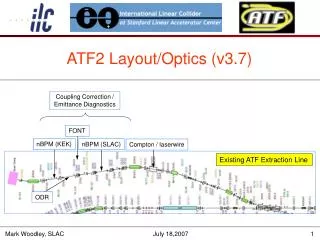
Emphasis on the optimal layout • Extend diagnostics section New final focus
Optimal layout • Better optics • Allow extension of diagnostics section • about 13m of additional space is possible • Better location • Avoids many issue • Give more suitable schedule for the international partners to find their contribution
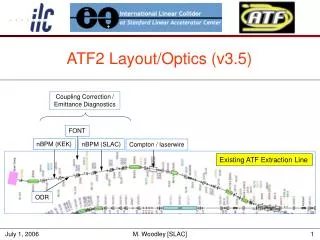
Coupling Correction and Emittance Diagnostics for the ATF2 Extraction Line, Mark Woodley • ideally • correction section with 4 independent skew quadrupoles, followed by • 2D (4 wire scanner) emittance measurement section • optics for orthogonal control of the 4 coupling phases • minimize εy once with each skew quadrupole • in present ATF extraction line • non-optimal optics in EXT straight section • wire scanners and skew quads interspersed • each wire scanner has x, y, and “u/v” (small angle, ~10°) wires + provide space for various experiments Coupling Correction / Emittance Diagnostics ATF Extraction Line FONT Compton / laserwire ODR nBPM nBPM
“Ideal” skew correction / ε diagnostic section SQ SQ SQ SQ WS WS WS WS – x – y 90° 90° 180° 90° 90° 90° 45° 45° 45° 45° 45° 45° See http://www.slac.stanford.edu/cgi-wrap/getdoc/slac-pub-8581.pdf
Existing extraction line diagnostic section WS WS WS WS WS SQ SQ SQ SQ – x – y L = 11.43 m 5° 8° 13° 20° 30° 36°
“Ideal” skew correction / ε diagnostic section for ATF2 Mark Woodley SQ SQ SQ SQ 1.2 1.2 1.7 1.7 1.1 1.3 1.1 0.9 0.9 0.9 0.7 1.3 1.1 WS WS WS WS WS – x – y 32° 48° 51° 21° 32° 58° 58° 32° L = 20.58 m ΔL ≈ 10 m σWS > 5 μ
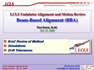
Tuning of ATF2 final focus • Procedure for ATF FF would be based on methods implemented at SLC FFS and FFTB, developed further • beam-based alignment using, e.g., shunting method • verify first order optics with trajectories fits • fix the phase advance between sextupoles • set sextupoles to minimize chromaticity • use global tuning correctors (knobs) to tune both the first-order and the nonlinear corrections using beam size measurements • Extensive simulations of tuning for GLC/NLC and TESLA, but not always all possible sources of errors were included • e.g. position errors included but not field strength, or vice versa • Simulations of the ATF2 tuning procedure started by UK colleagues, James Jones et al.
Analysis of Multipole and Position Tolerances for the ATF2 Final Focus LineJames Jones, ASTeC, Daresbury Laboratory • Analysed tolerances for all multipole components up to 20pole -> will be used to optimize magnet designs • Start analysis of position tolerances, including the effects of orbit correction and tuning knobs -> jitter and static position tolerances
Field Tolerances – Individual Quads Multipole Errors • Tolerance for 10% beam growth due to the multipole field in an individual magnet, in units of • Multipoles from: • Order 10 (20 pole) : Red.. • Order 5 (10 pole): Light Green.. • Order 2 (Quad): Orange Normal Skew
Position Tolerances – effect of individual magnets 2% Increase in beam size OR 2% change in position[beamsize] 2% Increase in beam size ONLY • Global tolerances are be determined considering the combined effect of all elements, including capabilities of correction methods • The global tolerances will need to match the goals A and B of ATF2 • 30% beam jitter for goal A and 10% (or a bit more?) beam size increase • for goal B, rely on intra-train feedback to reduce jitter, or aim to reduction of beam jitter to ~5% by providing better stability? Tolerance [mm-1] Tolerance [mm-1]
Effect of all quads (jitter) • Look at the results without the final doublet as these have the tightest tolerances • More likely to be specially mounted and aligned • Quadrupoles only (2% change of IP position) • X-plane: 14.5nm • Y-plane: 0.87nm • Roll Angle: 6.9rad • If we aim for 30%, this scales to ~12nm in verticalthe goal of 5% would corresponds to ~2nm • Feasibility of the latter, especially, need to be determined
Position Tolerances with correction • Assuming that the correction system will maintain the beam at the correct position, and looking only on beam size increase: • Quadrupoles only (2% increase) • X-plane: 585 nm • Y-plane: 197 nm • Roll Angle: 1.48 rad • Start developing tuning knobs (x, y, x waist , y waist ) and orbit correction and include them into procedure (no coupling correction yet) • Quadrupoles only (2% increase) • X-plane: 16 mm • Y-plane: 141 nm • Roll Angle: 3.5 rad • Procedure, knobs, orbit corrections, is being further optimized final tolerances will be then determined
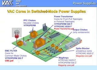
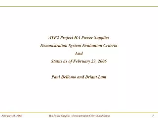
“Strategy for Commissioning the Beam” chapter of ATF2 proposal Frank Zimmermann’s questionnaire and some answers • Are all magnets on movers? yes • Are there dipole steering correctors? yes, several. Optimal locations TBD • How many BPMs and are they tightly attached to magnets attached to all quads, sextupoles and bends • Are there beam loss monitors and current monitors (toroids)? Yes. Location? • Are all magnets on individual power supplies? Yes. • Do we have conventional wire scanners and/or screens/profile monitors? Yes. Locations and how many? • What other existing diagnostics may be suitable for the commissioning? • Does the various diagnostics, including BPMs, read out bunch by bunch or single bunch or integrated over a train?
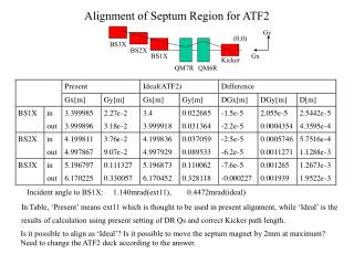
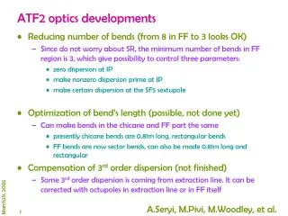
Other minor optics improvements needed • To make the design more construct-able: • change bends from sector bends to rectangular • use 0.8m bens (as used in ATF) instead of 1m for better field stability and more space • space near octupoles is too tight modify • QM14 is the strongest quad, and is close to max field of BT quads reoptimize
Summary • Between now and BDIR workshop the team will concentrate on the optimal layout + extended diagnostics optics, continue development of the tuning methods and finalize the numbers for tolerances