Download
1 / 13
130 likes | 256 Views
Modeling of Electrostatic Lithium Injection, Current Progress. P. Fiflis, D. Andruczyk , V. Surla , D.N. Ruzic. Introduction to ELI Concept Modeling Objectives Progress and Current Status of Model Modeling Results Conclusion. Introduction.

E N D
Modeling of Electrostatic Lithium Injection, Current Progress P. Fiflis, D. Andruczyk, V. Surla, D.N. Ruzic
Introduction to ELI Concept • Modeling Objectives • Progress and Current Status of Model • Modeling Results • Conclusion
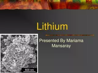
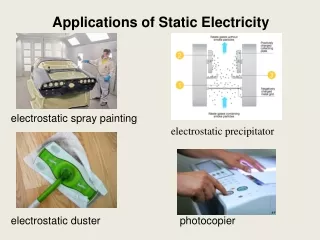
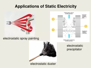
Introduction • Li has shown some excellent properties as a PFC material • Hydrogen getter • Improved Performance • Suppresses ELMs • Reduces damage on surfaces that have been coated with lithium • NSTX and LTX are currently active machines that use lithium as a PFC material • Currently deposited using LITER, a lithium evaporation system • However the center stack is one area of NSTX that is not reached by LITER • LITER line of sight • Center-stack is thin, small target that cannot be uniformly coated • Center-stack can be biased up to 2500 V • A possible solution to this problem may lie in the electrospray concept • Electrospray is currently used to produce a charged spray, which with proper application of an electric field, could be used to “paint” the center stack of NSTX
Introduction • The original intent was to paint the center stack by varying the bias on the center stack while creating a spray of charged droplets. • Between shots or before running • Coat the surface of the center-stack by varying the bias or by changing the pressure in the dropper. • Basic kinematics should be able to predict the path the particles will take and whether the center stack can be reached. • Solving for F = mg and F = qE = qV/d • where z0 = h, the height. ELiI E Bias
ELI Prototype ELiI Tube ELiI Chamber Plate Chamber Bias Plates
Introduction • Early ideas revolved around using this to coat a tokamak with lithium between shots. However, suggestions have been made to examine the use of an electrostatic lithium injector (ELI) during plasma operation. • Modeling work is being done to investigate the possibility of using time dependent electric fields to manipulate the trajectory of a charged lithium droplet within a tokamak to be able to use an electrostatic lithium injector for repair of PFCs and ELM control.
Modeling Objectives • The model seeks to solve the equations of motion in cylindrical coordinates (r, θ, z) for a charged lithium droplet: • Currently, only the toroidal magnetic field, Bθ, is taken into account. Future simulations will include poloidal fields and will be able to account for any magnetic field profile that can be input.
Progress and Current Status • The first step in the solution of these equations is solving Laplace’s equation, , for the inside of the tokamak, to find the voltage and subsequently, the electric field. • Laplace’s equation was solved for iteratively, using a second order central difference scheme. The results for a spherical tokamak with the dimensions of NSTX are shown: Voltage Profile (R-Z Cross Section) Voltage at Mid Height as a Function of Radius
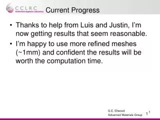
Progress and Current Status • Next, the user inputs a desired path r(z) for a charged lithium droplet to take. • The program uses a test acceleration in the z direction to attempt to find the center stack voltage as a function of time. • However, limitations on the ability of a voltage on the centerstack to reproduce this test acceleration as well as a desired path in r and z require the program to iterate over the acceleration vector several times to find the proper voltage and z-acceleration for the desired track. • The program then returns the required center stack voltage as a function of time for the particle to follow the track in r and z. • Currently, the program can only calculate the required voltage to make a droplet take a circular arc, a line, or a sine wave as a path. But with minimal additional work, any twice differentiable path of r(z) may be produced.
Modeling Results Lithium Particle Trajectory and Required Voltage for Circular Arc in r,z of Radius 1.4 m
Modeling Results Lithium Particle Trajectory and Required Voltage for Line of Slope r/z= -0.3
Modeling Results Lithium Particle Trajectory and Voltage for Sine Curve of Period .4 m and Amplitude of .2 m
Conclusion • An injected charged lithium droplet, can, with proper application of a time dependent voltage to the center stack, be made to take an arbitrary path through a tokamak. • The model is still in progress, and updates will include addition of poloidal and position dependent toroidal magnetic fields. • Proper application of this program, as well as further development of the electrostatic lithium injector may allow for online repair of plasma facing components and possibly even ELM control by transporting charged lithium particles around the plasma along an arbitrary path through the tokamak.