Download
1 / 27
360 likes | 588 Views
RADAR TRACKING SYSTEMS. Radar Tracking Systems. Objectives. Describe how a radar servo tracking system keeps the antenna pointed at the target.

E N D
Objectives • Describe how a radar servo tracking system keeps the antenna pointed at the target. • Distinguish between single beam, dual beam and monopulse tracking system and identify which system is accurate enough for use in a fire control system. • List and explain the 6 functions of the TWS system • Outline how the 3 tracking gates used by the TWS system generate position information for a target from initial acquisition through a turn.
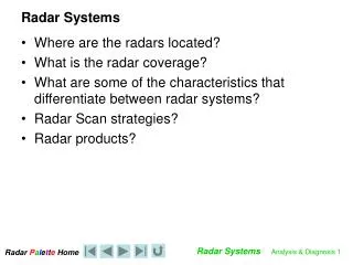
The “Problem” • Locating, Tracking and Engaging faster, more maneuverable targets from platforms that roll, pitch and yaw (рыскать)! • Limitation of sensor capabilities • Search Radar • Fire Control (FC) Radar
FC Radar Servo Tracking Systems • Motor – physically rotates antenna. • Electro-hydraulic motor for large systems. • Electric motors for smaller systems. • Servo-mechanism – controls direction of antenna rotation. • Receives two inputs: • Tracker – azimuth to point at. • Antenna position sensor – where antenna is pointed.
FC Radar Servo Tracking Systems • Tracker – determines target azimuth and antenna position error (magnitude and direction). • Single beam system. • Dual beam system. • Monopulse. • Gyro – Provides a stable reference for system. • Negates roll, pitch and yaw. • Data smoothing.
Servomechanism Order to Motor Controller Tracker Output Position Sensor Move Antenna Servo
Tracking – Single Beam Target location at the point of max return. Insufficient accuracy for weapons delivery
Tracking – Dual Beam Ideally, target centered between two beams. • Improved accuracy over single beam system • Sufficient accuracy for weapons delivery.
Tracking - Monopulse • Essentially 2 Dual beam systems • One Azimuth • One Elevation • High accuracy • Used for fire control tracking.
Range Tracking/Gates • Merge of Dual Beam FC tracking system with a integration computer. • Provides continuous info as to target’s “predicted” position. • Early gate. • Late gate. • Based upon abilities of FC technician, can Range Track • more than one target.
Fire Control Radar Tracking Problems • Fire Control tracking always “lagged” Fire Control problem. • Target possibly knows it’s being tracked by a fire control radar. • Hence commence evasive maneuvers
Solution Track – While – Scan (TWS)
Concept of TWS • Incorporate a search radar and a computer. • Radar continues to perform primary functions of search (scanning) and determines target position. • Radar sends position data to the tracking computer. • Computer performs target tracking calculations on all target data provided. • System is able to accurately predict target position. Track While Scan (TWS) • LEAD the Target!
Fundamentals of TWS • Target detection • Track initiation and track file generation • Generation of tracking “Gates” • Target track correlation • Track gate prediction • Display Six Basic Functions:
Target Detection • Automatic Detection and Tracking (ADT). • Digitizes (0’s and 1’s) scan area of search radar. • Each position in search area given specific digital “address”. • Once radar return received by ADT, FC solution generated for specific “address”.
Track Initiation and Track File Generation • Track file generated to store position (address) and gate data for each track. • Generation begins with initial storage of position (address) data. • Lat / Long. • Course / Speed. • Bearing / Range /Altitude. • Estimated Position (EP) data. • Correlating data (from own ship).
Gate Generation Tracking Gate Predicted Position Turning Gate Measured Position • Acquisition Gate (Largest) • Tracking Gate (Smallest) • Turning Gate
TWS Gates Acquisition Gate 10 degrees 10 degrees 2000 yards
TWS Gates Tracking Gate 1.5 degrees 1.5 degrees 120 yards
TWS Gates Turn Detection Gate Tracking Gate *Dimensions of this gate are determined by computer based on speed of target.
TWS Processing Original Course Turn Gate Reacquire Target Tracking Gates Resume Tracking Acquisition Gate
Track Correlation • System Resolution Rules. • Software decisions based upon threat environment and ROE. • Ambiguities resolved for: • Multiple gates on same target. • Multiple targets in same gate. • Crossing targets. • Computer has algorithms to sort out conflicts (e.g., contacts swapping identification during merge) • Operator must check computer results
TWS Radar System Advantages • Automated tracking • Track prediction • Tracks multiple targets simultaneously • Tracking info used to compute FC solution • Tracks with only a search radar and a computer
Real World Applications • AN/SYS-2 IADT (Integrated Automated Detection and Tracking) • Carriers • CG • DDG • FFG
Tracking Recap • Servo tracking systems can only handle a few, maybe just one, track(s) • Likely lag the problem (fire solution slow/inaccurate) • Wait for an update (radar hit) to re-position antenna and target plot • Track While Scan systems can easily handle multiple targets • Keep targets within predicted volume in space • System is projecting ahead to where the target should be next