Download
1 / 17
180 likes | 400 Views
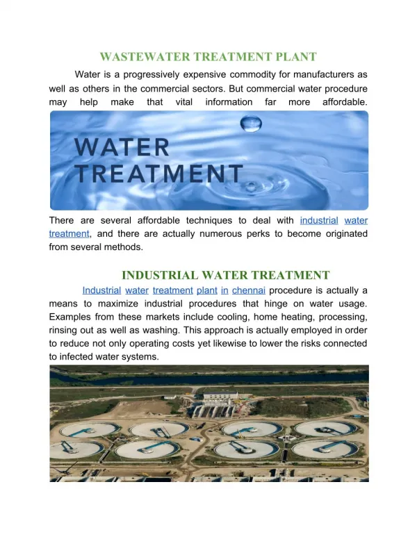
Surface Water Treatment Plant. …A Closer Look. Prepared by Dr. Richard O. Mines, Jr., P.E. Mercer University Environmental Engineering Department 1400 Coleman Avenue Macon, GA 31207. Influent Structure, Screens & Grit Removal Systems.

E N D
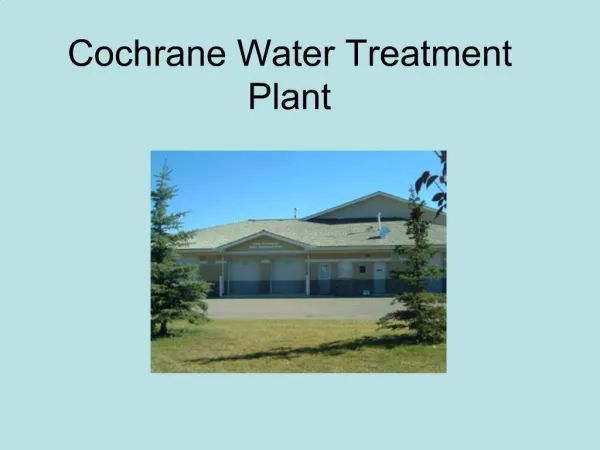
Surface Water Treatment Plant …A Closer Look Prepared by Dr. Richard O. Mines, Jr., P.E. Mercer University Environmental Engineering Department 1400 Coleman Avenue Macon, GA 31207
Influent Structure, Screens & Grit Removal Systems Raw water enters the inlet structure on the east bank of the river and flows by gravity to the traveling screens at the grit chamber before being pumped up to the reservoir by one of three centrifugal pumps. Figure 1 shows the influent structure and river.
Influent Structure, Screens & Grit Removal Systems (cont.) Figures 2 & 3 show the mechanical screens and grit removal system.
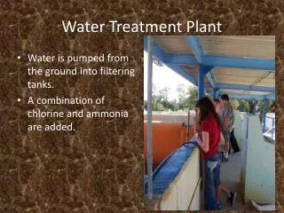
Influent Pumping Station After passing through the grit chamber and screens, the water is pumped up to the reservoir, by one of three centrifugal pumps. Figure 4 shows the centrifugal pump motors, which provide energy to pump the water from the river to the reservoir.
Reservoir and Intake Structure Water is pumped into the reservoir to allow additional time for suspended matter to settle out of the water (turbidity). Also the reservoir provides additional storage capacity doing times of drought. Figure 5 shows the reservoir. The intake structure allows water to be taken from the reservoir at different levels and pumped to the water treatment plant.
Reservoir and Intake Structure (cont.) Figure 6 shows the Reservoir Intake Structure and pumps. Figure 7 shows the pipe going to the water treatment plant.
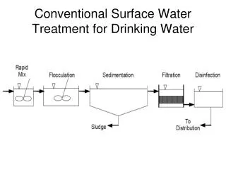
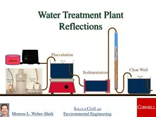
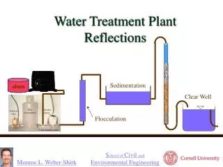
Rapid Mixing, Coagulation, and Flocculation From the reservoir intake structure, the water is pumped to the rapid mixing basin. Different types of chemicals are injected into the influent pipeline and are mixed instantaneously by the rapid mixer shown in Figure 8. Rapid mixing normally takes 60 seconds or less. Alum, lime, and chlorine dioxide are some of the typical chemicals added to surface water. These chemicals react with turbidity, microorganisms, and hardness so that large particles called “floc” can be removed by sedimentation.
Rapid Mixing, Coagulation, and Flocculation (cont.) Coagulation is the process of adding chemicals to neutralize charge on particles and precipitate other particles out of solution. The large floc particles form during the flocculation process in which slow stirring or mixing occurs. Flocculation generally takes around 20 to 30 minutes to occur. Figure 9 shows the flocculation chambers.
Rapid Mixing, Coagulation, and Flocculation (cont.) Figure 10 shows the “flocs” that are forming. Figure 11 shows the chemical storage tanks with a containment wall around them so chemicals cannot be accidentally released to the environment.
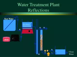
Sedimentation After flocculation, the water flows by gravity into the settling basins where the large particles or “flocs” settle out of the water by the force of gravity. The particles that are removed (sludge) flow by gravity to a gravity thickener to increase the solids concentration in the sludge. Treated water then flows by gravity to the dual media filters. Figure 12 shows the settling basins. Figure 13 shows the effluent weirs.
Dual Media Filters After sedimentation, the water flows by gravity to the dual media filters. The filters remove additional suspended solids that were not removed during sedimentation. Disinfectants such as chlorine or chlorine dioxide may be added to the incoming water. Figure 14 shows a filter during the filtration process Figure 15 shows the backwash water trough.
Chlorine Addition and Storage After filtration, the water flows by gravity to another rapid mixer where additional disinfectant such as chlorine is added to provide chlorine residual in the water. Figure 16 shows the rapid mixer. From the rapid mixing basin, the water flows by gravity into one of four 5-million gallon storage tanks, where, the disinfectant has sufficient contact time with the water to ensure that pathogens are killed.
Chlorine Addition and Storage (cont.) Figure 17 shows the 5-million gallon, domed storage tanks. Normally, the contact tank or storage tanks are called the “clear well”. From the storage tanks the water flows to the high service pumping station, which pumps the water throughout the water distribution systems. Additional disinfectant such as chlorine or chlorine dioxide may be added at the pumping station to provide chlorine residual in the distribution system and prevent re-growth of pathogens and bacteria in the system.
Sludge Handling and Treatment Suspended solids, chemical precipitates, and microorganisms that end up in the sludge in the sedimentation tanks are pumped to the gravity thickeners. The gravity thickeners provide several hours of quiescent settling so the sludge can thicken to a higher solids concentration. The thickened sludge is approximately, 5 to 8 % solids. Figure 18 shows a gravity thickener.
Sludge Handling and Treatment (cont.) Supernatant, the liquid portion of the sludge is pumped to artificial wetlands for further treatment before seeping into the groundwater. Figure 19 shows a propeller mixer on a guide-rail. The mixer is used to stir the contents of the tank if necessary and can be rotated in several directions.
Sludge Handling and Treatment (cont.) The thickened sludge is then pumped to the solids handling building where plate and frame presses are used for dewatering the sludge. Figure 20 shows the solids handling building. Additional water is removed from the sludge and the solids content is increased to approximately 30 % solids.
Sludge Handling and Treatment (cont.) Figure 21 shows a picture of the sludge produced at a typical water treatment plant. It is normally applied to agricultural land to help stabilize the pH.