Download
1 / 17
170 likes | 217 Views
Engine Breathing. P M V Subbarao Professor Mechanical Engineering Department. Measure of Filling & Emptying Effectiveness…. A Global Measure of Breathing Effectiveness.

E N D
Engine Breathing P M V Subbarao Professor Mechanical Engineering Department Measure of Filling & Emptying Effectiveness….
A Global Measure of Breathing Effectiveness • Volumetric efficiency a measure of overall effectiveness of engine and its intake and exhaust system as a natural breathing system. Volumetric efficiency is defined as:
Significance of Reference Density • If the air density a,0 is evaluated at inlet manifold conditions, the volumetric efficiency is a measure of breathing performance of the cylinder, inlet port and valve. • If the air density a,0 is evaluated at ambient conditions, the volumetric efficiency is a measure of overall intake and exhaust system and other engine features. • The full load value of volumetric efficiency is a design feature of entire engine system.
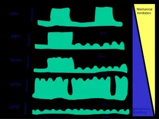
1 2 3 Transient Pressure in manifolds & Cylinder Exhaust Pipe
Transient Pressure in Manifolds 4800RPM 1200RPM
FUEL A I R Computation of Intake Process : SI Engine SI Engine
FUEL A I R Total Mass of mixture inhaled during Intake Process
Computation of Exhaust Process : SI Engine Combustion Products Exhaust Stroke
Stream Tube formed by Flow Through Valves Equivalent Converging-Diverging Nozzle Configurations: Mild Separation. Severe Separation
Instantaneous minimum Available Flow area: Low Lift • For low lift valves, the minimum available flow area corresponds to a frustum of right circular cone. • The annular space between valve and seat forms the minimum flow area perpendicular to the seat. The range of valve lift for generation of right angle cones The minimum area is:
For the second stage, the minimum area is still the frustum of a right circular cone. However, this flow area is not perpendicular to the valve seat. The base angle of the cone increases from (900-) toward that of a cylinder. For range of valve lift for this stage: Instantaneous minimum Available Flow area : Intermediate Lift Dmis mean diameter of seat :
Instantaneous minimum Available Flow area : High Lift • When the valve lift is sufficiently large, the minimum flow area is no longer between the valve head and seat. • It is the port area minus the sectional area of the valve stem. Then,