Download
1 / 80
950 likes | 1.63k Views
Engine Breathing Chapter 12. DSL 131. OBJECTIVES. Identify the intake and exhaust system components. Describe how intake air is routed to the engine’s cylinders and how exhaust gases are routed out the tailpipe. Define the term positive filtration.

E N D
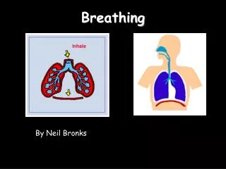
Engine Breathing Chapter 12 DSL 131
OBJECTIVES • Identify the intake and exhaust system components. • Describe how intake air is routed to the engine’s cylinders and how exhaust gases are routed out the tailpipe. • Define the term positive filtration. • Outline the operating principle of an air precleaner. • Service a dry, positive air cleaner. • Perform an inlet restriction test. • Identify the subcomponents on a truck diesel engine turbocharger. • Outline the operating principles of an exhaust gas-driven, centrifugal turbocharger. • Explain how a compounded turbocharger functions.
OBJECTIVES (Cont.) • Troubleshoot common turbocharger problems, and perform some basic failure analysis. • Define the role of a charge air cooler and the relative efficiencies of each type. • Test a charge air heat exchanger for leaks. • Relate valve configurations and seat angles to breathing efficiency and cylinder gas dynamics. • Describe how a pulse-type exhaust manifold can boost turbocharger efficiency. • Outline the function of a pyrometer on a truck diesel engine.
OBJECTIVES (Cont.) • Describe the role of the exhaust silencer and its operating principles. • Comprehend the nature of sound dynamics and how combustion noise is minimized in an engine. • Understand some basic exhaust gas emissions chemistry. • Describe the operation of a diesel engine catalytic converter and EGR system.
INTRODUCTION • Over the years, the intake and exhaust systems on commercial diesel engines have become more interconnected because of the universal use of turbochargers and exhaust gas recirculation (EGR) systems, so it makes sense to group them together in one chapter and call it Engine Breathing. • Turbochargers boost the intake manifold at pressures above atmospheric. • Use rejected exhaust heat. • EGR (exhaust gas recirculation) • Routes spent exhaust gas back to the intake to reduce combustion temperatures. • Aftertreatment Systems • Catalytic Converters • Diesel Particulate Filters (DRT) • Naturally Aspirated Engines • Induction Circuit • Turbo/Manifold Boosted Engines • Intake circuit
GAS FLOW IN BREATHING CIRCUIT Overview of the gas flow in a typical post-2007 engine breatingcirckuit.
ROLE OF INTAKE SYSTEM • The function of the air intake system in a diesel engine is to supply a charge of air or air/dead gas mixture to the engine cylinders for combustion, cooling, and scavenging. • Air charged to the cylinders often substantially exceeds that required to combust the fuel. • Great for power • Bad for emissions. • All engine outcomes are managed for emission reductions. • Shown at right • Right-side view of a post-2010 Mack Truck engine. • Notice the cutaway turbocharger and EGR circuits
ROLE OF THE EXHAUST SYSTEM The function of the exhaust system is to minimize both engine noise and noxious emissions while restricting the exhaust gas flow to a minimum degree. Turbocharger is a component of both the intake and exhaust systems. Uses rejected exhaust heat to power a compressor and pressurize the engine cylinders. All current highway engines have complex systems to manage emissions. Show at right: Components of a pre-2004 breathing circuit when engines were more simple.
INTAKE SYSTEM COMPONENTS • Precleaner • Main filter • Intake ducting/piping • Turbocharger(s) and turbocharger controls • Charge air cooling circuit • Intake module for mixture management of EGR • Intake manifold • Valve porting and intake tract design
Exhaust system components • Valve configuration and exhaust tract geometry • Exhaust manifold • Turbocharger(s) and turbocharger controls • EGR system • Exhaust piping • Catalytic converter(s) • DPF system • SCR system • Muffler
AIR CLEANERS • The function of the air cleaner system on a highway diesel engine is to filter airborne particulates from the air that will be delivered to the engine cylinders. • Precleaners: • Required in trucks operating in dusty conditions or in North American winter conditions, especially where highways are salted. • Can triple the service life of the main engine air cleaner. • Generate cyclonic flow to separate heavy particulates by centrifugal force.
AIR CLEANERS • Dry, Positive Filters. • Used in all contemporary North American commercial vehicle diesel engines. • Positive means all air must pass through the filtering media. • Usually resin impregnated pleated paper. • 99.5% filtering efficiencies. • Best efficiency immediately prior to replacement becoming necessary.
Dry Element Air Filter Replacement Dry paper filters are designed to last for as long as 12 months in linehaul applications. Normally they are not replaced until they become restricted/clogged.
Servicing Air Filters A filter mounted inlet restriction gauge (aka filter minder).
Manometer A manometer is used to measure restrictions to airflow in a filter housing. Usually a clear glass or plastic u-shaped tube around a calibration scale. More accurate than a “filter minder”
TECH TIP • One of the first tests that should be performed when troubleshooting black smoke emission from an engine is to check inlet restriction. • If the onboard restriction gauge is reading high, fit an H2O manometer or negative pressure gauge to confirm the reading. • The engine should ideally be tested under load, but a throttle snap to high idle may provide some clues… • One OEM suggests that a throttle snap on an unloaded engine, is roughly equivalent to 50% of the full load, rated speed specification.
Laundering Dry Element Filters • Professional laundering is perhaps a second best, but necessary option to replacement. • Dusty construction sites, desert operations (military?) may clog the filter in days. • Process: • Filter soaked in detergent solution. • Rinsed (from inside) with low pressure water. • Dried thoroughly • Tested for integrity. • OEM testing of professionally laundered filters shows efficiency reductions each time the filter is cleaned. • Shown at right is a special air filter cleaning machine.
OIL BATH FILTERS—VISCOUSIMPINGEMENT OIL FILTERS Low operating efficiencies have made these types of nonpositive filters things of the past. You will only see them on much older highway diesel engines and possibly on some off-highway engines. Only efficient at rated engine speed. Efficiency falls off at lower speeds
TURBOCHARGERS • Used universally on North American medium and large bore highway diesels. • Nearly universal on small bore engines. • Definition: • An exhaust gas-driven, centrifugal pump that “recycles” some of the rejected heat from the engines cylinders. • May exceed 200,000 rpm in some racing applications (30% lower in diesel engines) • Turbo-compounding is used on some Detroit Diesel engines..
PRINCIPLES OF OPERATION • A Turbocharger is an exhaust gas-driven air pump consisting of a turbine and an impeller mounted on a common shaft. • The figure at right shows the gas and lubrication flows through a simple turbocharger.
TYPES OF TURBOCHARGERS • Constant geometry (CG) • All the exhaust flow is routed through the turbine housing regardless of how the engine is being operated. • Variable geometry (VG) • Uses either internal or external controls to either manipulate the flow through the turbine housing or to allow some exhaust to bypass the turbine. • Currently nearly all turbochargers sue some means of varying exhaust flow through the turbine housing.
Warning • Mismatching of CG turbochargers may result in high engine cylinder pressures that result in engine failure or, conversely, in low power, smoking, and high noxious emissions.
VARIABLE GEOMETRY TURBOS • VG turbo types: • Wastegate controlled • When intake pressure reaches a desired level, exhaust gasses are allowed to bypass the turbine limiting total boost. • Volute controlled • AKA Variable inlet guide vane.
CONSTANT GEOMETRY TURBOCHARGERS • Designed for optimum output at a specific rpm/engine load. • May overboost at high rpm/load. • May lag at low rpm/load.
The Objective of all VG turbos • Allow the turbo to act like a small turbocharger when engine loads are light. • Allow the turbo to act like a large turbocharger when engine loading is high.
Wastegate Controlled • Have been around for a long time. • Pneumatic: Wastegate movement depends on manifold pressure. • See illustration below • Electronic: Wastegate is positioned by the ECM.
Volute Controlled VG Turbo • Changes the angle of the turbine inlet guide vanes, increasing or decreasing the velocity of the exhaust gasses as necessary.
Turbocharger Precautions • Avoidance of hot shutdown • Prelubing • Some OEMs require that the oil filters be primed when replacing them at service intervals.
Turbocharger Failures • Hot shutdown • Turbocharger overspeed • Air intake system leaks • Lubrication-related failure
CHARGE AIR HEAT EXCHANGERS • The objective of charge air coolers (CACs), whatever their cooling medium, is to cool the air pressurized by the turbocharger.
CAUTION • Never regulate the air pressure at a value above 30 psi (200 kPa) when testing for boost side leaks because this may result in personal injury and damage to the components under pressure.
EXHAUST GAS RECIRCULATION • From 2007 onward, all the diesel engine OEMs are using some form of EGR.
EGR OPERATING PRINCIPLE • An EGR system routes some of the exhaust gas back into the intake system.