Download
1 / 49
490 likes | 653 Views
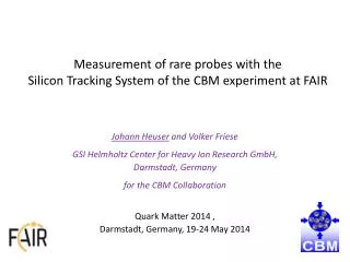
Status of the CBM Silicon Tracking System. Johann M. Heuser CBM Collaboration Meeting GSI, 15 April 2010. 13 contributions from STS team. covering simulations, beam test, detector tests, radiation hardness, demonstrator module, ladder + station engineering, FEE. STS Workgroup.

E N D
Status of the CBM Silicon Tracking System Johann M. Heuser CBM Collaboration Meeting GSI, 15 April 2010 J.M. Heuser − Status of the Silicon Tracking System
13 contributions from STS team covering simulations, beam test, detector tests, radiation hardness, demonstrator module, ladder + station engineering, FEE J.M. Heuser − Status of the Silicon Tracking System
STS Workgroup J.M. Heuser − Status of the Silicon Tracking System
STS stations • area, 8 stations: 3.2 m2 • number of sensors: 1068188 sensors, 2 cm × 6 cm 166 sensors, 4 cm × 6 cm 714 sensors, 6 cm × 6 cm • number of sectors: 756 • number of r/o channels: 1.5 106 • number of FE chips: 1.2 104 J.M. Heuser − Status of the Silicon Tracking System
Engineering of STS modules & stations Y. Murin CBM-MPD STS Consortium J.M. Heuser − Status of the Silicon Tracking System
STS – mechanical support Building on technology developed for the ALICE Strip Tracker Consortium - S. Igolkin, StPbU front view of a (half)-station ALICE ITS carbon fiber structure module front top view of a station J.M. Heuser − Status of the Silicon Tracking System
STS assembly details attaching sensors to carbon fibre support J.M. Heuser − Status of the Silicon Tracking System
STS ladder assembly J.M. Heuser − Status of the Silicon Tracking System
STS ladder mockup J.M. Heuser − Status of the Silicon Tracking System
Development of tracking modules tab-bonding of cables to detectors and front-end board Microstrip sensors double sided, CBM01/CBM03 Readout cables * 4-layer* Al-14 m on Kapton-10 m * Shield + spacer layer * 1024 lines, 100-120 µm pitch* up to 60 cm long Front-end board bump-bonded low-power FE chip on a high-density circuit J.M. Heuser − Status of the Silicon Tracking System
Module demonstrators 1-b' J.M. Heuser − Status of the Silicon Tracking System
we have: work hypothesis of STS layout emerging engineering solutions on ladder and station construction beginning prototype work we need: to consolidate the concept build proof-of-principle ladder in 2011-2012 matching components timely availability of components for this work J.M. Heuser − Status of the Silicon Tracking System
STS station layout and simulation of the hit recognition performance 14 A. Kotynia • 1024 strips per sensor; • 15° stereo angle; • 60 µm strippitch; J.M. Heuser − Status of the Silicon Tracking System • Sensors: • 6 cm wide; • 2-6 cm high;
Complete chain of physical processes caused by charged particle traversing the detector Magnetic field influences collection of the charge on the strips 15 Realistic STS Digitizer • |B| = 1T • Holes: • = 1.5° Dx = 8mm Electrons • = 7.5° Dx = 40mm • Particle position in the sensor is obtained by using Center Of Gravity algorithm: • Random noise is added according to a Gaussian distribution with standard deviation as an equivalent noise charge of the detector system J.M. Heuser − Status of the Silicon Tracking System
16 STS Digitizer – collected charge per strip J.M. Heuser − Status of the Silicon Tracking System
17 Hit Finding Efficiency large incidence angle J.M. Heuser − Status of the Silicon Tracking System
Channel dead time simulations For minimum bias Au+Au collision at 25AGeV channel occcupancy: J.M. Heuser − Status of the Silicon Tracking System
19 19 ADC resolution J.M. Heuser − Status of the Silicon Tracking System
we have: realistic model of the STS various varations to it insight in effects on the hit finding efficiency and creation of data volume we need: to further optimize the overall system station layout use the reconstructed hits or hit channels efficiently in the tracking (interface optimization, new stations, ...) overall performance counts J.M. Heuser − Status of the Silicon Tracking System
Performance test of STS demonstrators A. Lymanets 15th CBM collaboration meeting, April 12th, 2010 J.M. Heuser − Status of the Silicon Tracking System
FEB rev. B: • Every second channel bondable. • Still good for lab tests for timing studies or • ADC response (without clustering). • FEB rev. C: • All channels are usable • But thermal stability becomes an issue. • Detector-FEB cable: • Turns out to work if shielded properly. • Detectors of CBM01 and CBM02 type • “behave” similarly (bad), poor charge • collection at n-sides. • FEB 4nx: • Cooling plates improve thermal stability • Problems with surviving potential of the chips • on board. • Beam time : vastly different count rates • in different stations caused by the beam. J.M. Heuser − Status of the Silicon Tracking System
Energy calibration with 241Am Using 300 μm pitch detector => no significant charge sharing Energy gain = 110.6 e-/ADC cnt + one can obtain pedestal energy (not necessarily zero) Noise 460 e- @ 6 pF J.M. Heuser − Status of the Silicon Tracking System
Calibration line Energy calibration is obtained, but extrapolated pedestal amplitude is ~3 kElectrons. Possible reasons: non-linearity, bias due to peak detector. J.M. Heuser − Status of the Silicon Tracking System
n-XYTER chip Power lines current Test channel Channel 0 Output pads Input pads Channel 127 current Power lines J.M. Heuser − Status of the Silicon Tracking System
Pedestal profile over channels Crosstalk problem digital crosstalk – on the chip, not just directly between channels • Pedestal “sag” is observed with maximum in channel #64 • To be addressed in the upcoming engineering run done in Heidelberg Univ. (H. K. Soltveit) J.M. Heuser − Status of the Silicon Tracking System
we have: experience with the first complete system chains developed lots of tools but also destroyed equipment we need: more objects, material, experienced fellows built new tracking modules overcome technology problems (e.g. PCBs at cutting edge designs) thorough long-term tests J.M. Heuser − Status of the Silicon Tracking System
Status of Front End Electronics: n-XYTER PCBs & Power Supply V. Kleipa J.M. Heuser − Status of the Silicon Tracking System
Modifications w.r.t. FEB_C: Increased NXYTER bond pitch 0.3V drop LDOs used Separated supply regulators PT100 sensor out Alternative connector for separated LVDs and common mode signals Testpoints New power connector I2C and SPI spike filter I2C reads now: Temperature Current Testchannels Slow, Fast I2C RW: Serial EEprom for data storage N-XYTER FEB rev. D 20 specimen under construction wire-bonding: C. Simons J.M. Heuser − Status of the Silicon Tracking System
Cooling Block for FEB_B, FEB_C and FEB_D Design by Carmen Simons n-XYTER PCB Cooling Plate C. Simons J.M. Heuser − Status of the Silicon Tracking System
Input pitch 100um PCB size 65mm x 80mm Cooling of 14W power with bottom copper or Al plate ADC device on bottom side Ext. power supply regulation Open task: Staggered NXYTER bonds to one layer input fan Data output connection n-XYTER Demonstrator r/o board J.M. Heuser − Status of the Silicon Tracking System
FEE boards are critical for system studies we have: hopefully now a reasonably stable board (rev. D) we need: to move from 1-chip general purpose board (n-XYTER) to intermediate 4-chip board for ladder tests (n-XYTER) to develop a concept and build a prototype of the 8-chip board (STS-XYTER) to do this: strengthen the team J.M. Heuser − Status of the Silicon Tracking System
Development of microstrip detectors J. Heuser J.M. Heuser − Status of the Silicon Tracking System
CBM02 (2008) CBM03 (2010) CBM01 (2007) (parallel: ISTC01) GSI-CiS Erfurt CBM04 (2010) close-up of a corner of CBM01 J.M. Heuser − Status of the Silicon Tracking System
Close-up of a corner of CBM03 J.M. Heuser − Status of the Silicon Tracking System
we have: essentially one vendor/production partner (CiS) used CBM01 and CBM02 for prototyping work indications that the charge collection is not fully efficient and understood set up framework for TCAD simulations we need: to verify the charge collection properties overcome stability issues to set up a systematic characterization, new material coming (CBM03, CBM04) systematic irradiation studies J.M. Heuser − Status of the Silicon Tracking System
Development of radhard microstrip detectors S. Chatterji J.M. Heuser − Status of the Silicon Tracking System
3D strip detector simulation model • 3-D TCAD simulation tools “SYNOPSYS” • Sub packages • Sentaurus • Inspect • Tecplot • SPICE (Mixed Mode) X-Y plane of the 3D grid. One can see there is a stereo angle on either side of 7.50. J.M. Heuser − Status of the Silicon Tracking System
Some Static Characteristics • CTotal = Cback+2*Cint • ENC αCTotal • Optimization needed to maximize breakdown voltage & minimize ENC J.M. Heuser − Status of the Silicon Tracking System
Optimizations of the detector design strip pitch and width strip insulation J.M. Heuser − Status of the Silicon Tracking System
Type Energy (eV) Trap σe (cm2) σh (cm2) η (cm-1) Acceptor Ec-0.42 VV 2.0*10-15 2.0*10-14 1.613 Acceptor Ec-0.46 VVV 5.0*10-15 5.0*10-14 0.9 Donor Ev+0.36 CiOi 2.5*10-14 2.5*10-15 0.9 Impact of Radiation Damage • VBD↑ with fluence • Current ↑ by 3 orders • Rint ↓ with fluence • Detailed study needed J.M. Heuser − Status of the Silicon Tracking System
Full system simulation transient signal behavior in the detector and in the readout cable J.M. Heuser − Status of the Silicon Tracking System
Beam pipe options in STS S. Belogurov J.M. Heuser − Status of the Silicon Tracking System
Be: 4 LHC experiments, Belle, Cleo, CDF etc. 0.3 - 0.5 mm typical thickness Al: HERAb 0.3 mm with stiffening ribs. Information availabe, seems reproducible Relevant background for window: LHCb VELO (Ø800 mm 2 mm Al alloy), machined from a forged billet together with the bellow. SF for the LHCb Be beam pipe is 4-6, for window ~ 3 SF for the HERAb beampipe is ~2 J.M. Heuser − Status of the Silicon Tracking System
Studied configurations “Ideal ” configurations. Effects: cylinder-cone; Be-Al. Al: window – scaling from VELO, cone – “simple” manufacturing. Remarks. 1) 0.3 mm Al = 0.5 mm Be 2) Competition works: JSC “Kompozit” started to think about 0.4 mm Be pipe “Realistic” configurations. Effects of bellows, width of “Tube”. 1.6º configuration fits to ladders of S. Igolkin without cutting the central rib. Any configuration has a weld 1x10 mm J.M. Heuser − Status of the Silicon Tracking System
Results for UrQMD central events at 25 AGeV Range distribution window welding J.M. Heuser − Status of the Silicon Tracking System
Results for UrQMD central events at 25 AGeV Comparison of Al and Be cones done as well for tubes No pipe Al tube will do ? System engineering, workshop in Fall 2010? /c No pipe Lambda p pi- K0 pi+ pi- /c J.M. Heuser − Status of the Silicon Tracking System
Project plan, iMoU, Writeups, TDR • Request by the Technical Coordinator: • Comprehensive Sub-System Note during Q3 2010 • Design Review during Q1 2011 (CBM organized, external Reviewers) • TDR's in Q1 2012 • Project plan within Interim Memorandum of UnderstandingDRAFT – being updated • Participating Institutes • Work share during R&D phase, Construction phase less clear • Tasks, timelines and deliverables • not covered tasks + teams • Costs • STS construction + commissioning timeline: adapt to new FAIR schedule J.M. Heuser − Status of the Silicon Tracking System
Test beam at GSI, 21-26 June 2010 preliminary – beam scheduling meeting on 19 April • cave C • beam line HTD • beam: Nitrogen • 0.8 GeV/u • on a target J.M. Heuser − Status of the Silicon Tracking System