Download
1 / 16
160 likes | 319 Views
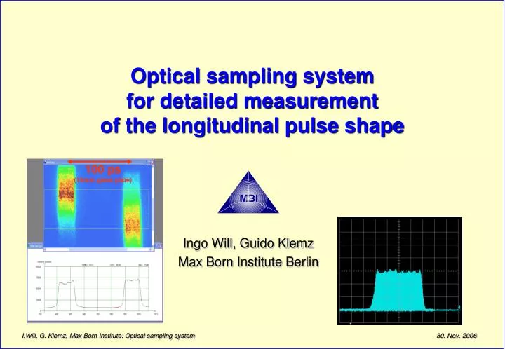
Optical sampling system for detailed measurement of the longitudinal pulse shape. Ingo Will, Guido Klemz Max Born Institute Berlin. 100 ps (10mm glass plate). Present status at PITZ: Pulse shape is measured using a synchroscan streak camera. Present limits: Streak camera signal is noisy

E N D
Optical sampling system for detailed measurement of the longitudinal pulse shape Ingo Will, Guido Klemz Max Born Institute Berlin 100 ps (10mm glass plate) I.Will, G. Klemz, Max Born Institute: Optical sampling system
Present status at PITZ: Pulse shape is measured using a synchroscan streak camera • Present limits: • Streak camera signal is noisy • Resolution limited: • Green light: to 2...4 ps • UV light: to 3…5 ps • Measurement is sensitive to illumination of the cathode • space-charge effects in the streak tube: pulse broadening to 60 ps • no direct measurement for IR • modification of the pulse shape in the amplifier chain cannot be investigated strong intensity noise of the streak camera time laser #2 resolution limited to 3..4 ps Measurement: Nov 03, 2003
Pre-compensation of changes of the pulse shape during amplification and conversion to the UV IR l = 1.047 mm green l = 0.524 mm UV l = 0.262 mm
Emicro = 3 mJ First regen Compensation of the drop by the drive current of the pump diodes, but the „pumping“ of the beam diamter remains! Emicro = 15 mJ Second regen 2ms (2000 pulses) Two-stage regenerative amplifier concept • Thermal lens in the power regen leads to a drop of the intensity to 50% during 2000 pulses • The two- or three-stage regen concept may enable us to apply advanced amplifier techniques (i.e. thin-disk amplifiers) Yb:KGW oscillator Yb:YAG regen Emicro = 3 mJ First regen DST shaper Drop due to thermal lensing Yb:YAG power regen Emicro = 15 mJ Second regen 2ms (2000 pulses)
Formation of flat-top laser pulses • Flat-top laser pulses • generate electron bunches with a flat-top shape in z-direction • -> improved brightness of the electron beam output pulses recorded with a streak camera:
Simple DST shaper forming flat-top laser pulses • Flat-top laser pulses • generate electron bunches with a flat-top shape in z-direction • -> improved brightness of the electron beam output pulses recorded with a streak camera:
Amplification of flat-top pulses from an Yb:YAG oscillator 100 ps (10mm glass plate) • Parameters of the pulses shown: • length of the train: 1.5 ms (1500 pulses) • Energy in the train: 27 mJ • Energy per micropulse: 18 mJ (at 1030 nm) • Streak camera measurement taken with SHG (at 515 nm) • Energy is ~ 4…5 times smaller than in the present Nd:YLF phothocathode laser • Increasing this energy is a major challenge to the laser designer Record of flat-top pulses with a synchroscan streak camera (Optronis, ~3...4 ps resolution) at 515 nm wavelength
Requirements for a system measuring the pulse shape Further progress in pulse shaping requires a measurement system with the following parameters: • Temporal resolution: better 1 ps • Suitable for IR, green and UV light • Clean signal, reliable measurement especially for: • the edges • the flatness of the pulse Question: How to build a system that displays the pulse shape in a real-time manner ?(complete measurement during each laser shot)
Different beam shapes depending on the alignment of the shaper These images are taken with 5 Hz repetition rate and displayed on an oscilloscope in a real-time manner
How does the optical sampling system work • Every sampling measurement system requires 1.periodic signals 2. a very fast gate3. Synchronization of the gate to the signal
Sampling measurement systems • Example of a sampling measurement device: Commercial RF sampling oscilloscopes • electrical switch based on very fast switching diodes • gating time (=resolution) reached with of today’s sampling oscilloscopes: t ~ 15 ps • Optical sampling system: • utilizes periodicity of the micropulses in the train(requires > 100 micopulses) • Fast optical gate: mixing with short laser pulses • Gating time (=resolution) determined by theduration of the pulses from the laser oscillator of the sampling system(at present: t= 0.5…0.6 ps) ~ 12 ps FWHM
~ 12 ps FWHM Sampling system presently used to measure the pulse shape in the IR
Stable synchronisation during the scan requires an embedded C++ state machine
Shortest pulses and bandwidth of this amplifier combination Emicro = 3 mJ • Output pulses of the KGW oscillator: t = 0.5 ps • Output pulses of the regen combination: t = 1.8 ps • Can pulses of this duration efficiently be transferred to the UV(forth harmonics, l = 258 nm) ? Yb:KGW oscillator 2ps Yb:YAG regen 12ps Emicro = 2x0.3 mJ Yb:YAG power regen Emicro = 2x7 mJ
edges < 2 ps ~ 14 ps FWHM Typical pulse shapes measured with the optical sampling system • Present status: • Sampling system operational in the IR (1030 nm) • work is ongoing to extend the measurement to the UV 6 ps 25 ps non-Gaussian pulse Gaussian pulse flat-top pulse
Summary • An optical sampling system is being developed at the MBI • displays the shape of ps pulses on a standard oscilloscopein a real-time manner • Based on cross correlation between the pulses to be measured and the femtosecond pulses from a KGW oscillator • Temporal resolution: 0.5 ps • Linearity in time: ~ 10% • The system utilizes the periodicity of the pulses of the photocathode lasers used at FLASH and PITZ • Work is ongoing extend the measurement range to the UV