Download

1 / 34
340 likes | 517 Views
OSI Physical Layer. Network Fundamentals – Chapter 8 Sandra Coleman, CCNA, CCAI. Objectives. Explain the role of Physical layer protocols and services in supporting communication across data networks.

E N D
OSI Physical Layer Network Fundamentals – Chapter 8 Sandra Coleman, CCNA, CCAI
Objectives • Explain the role of Physical layer protocols and services in supporting communication across data networks. • Describe the role of signals used to represent bits as a frame as the frame is transported across the local media. • Describe the purpose of Physical layer signaling and encoding as they are used in networks. • Identify the basic characteristics of copper, fiber and wireless network media. • Describe common uses of copper, fiber and wireless network media.
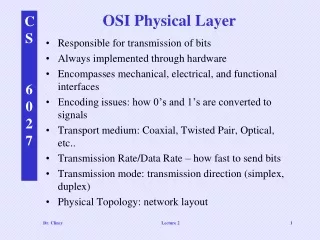
Physical Layer Protocols & Services • Purpose: create the electrical, optical, or microwave signal that represents the bits in each frame and get them on to the media. • This includes binary transmission, cable specifications, and the physical aspects of network communication.
Physical Layer Protocols & Services • Frames are taken from the Data link layer and converted into bits and then into the necessary signals depending on the actual physical networking media. These are retrieved and converted back at the receiving device.
Physical Layer Protocols & Services • 3 basic forms of network media: copper cable, fiber, wireless. • Copper – electrical pulses • Fiber – patterns of light • Wireless – patterns of radio transmissions
Physical Layer Protocols & Services • Physical layer standards are appropriately set by bodies who govern the hardware (relevant electrical and communications engineering organizations)
Physical Layer standards • 4 areas of physical layer standards • Physical and electrical properties of the media • Mechanical properties of the connectors (pinouts, materials, dimensions) • Bit representation by the signals (encoding) • Definition of control information signals • NICs, interfaces, connectors, cable materials and cable designs are all specified in these standards.
Fundamental Principles • Encoding – converting streams of data into bit patterns • Signaling – generating the signals (electricity, light, waves) that represent the “1” and “0” on the media.
Basic encoding techniques Non Return Zero – NRZ – low voltage=0, high voltage=1 Good for slow speed data links,Very susceptible to interference Manchester encoding – voltage transitions (low > high=1, high<low=0) - Good for 10BaseT Ethernet NRZ Manchester
Encoding • Coding groups – A code group is a consecutive sequence of code bits that are interpreted and mapped as data bit patterns. Allows detection of errors more efficiently. Can Tx at faster speeds. • Must have start/stop frame bits for this to work
Measuring data carrying capacity • Bandwidth – amt of info that can flow from one place to another in a given amt of time • Throughput – measure of transfer of bits across the media over a given period of time. Usually < bandwidth. Affected by amt of traffic, type of traffic, # networking devices encountered. Cannot be faster than the slowest link of the path from source to destination. • Goodput – measure of usable data transferred over a given period of time. Throughput – overhead (session establishment, acknowledgements, encapsulation, etc.)
Copper Media - interference • Shielding and twisting of wire pairs are designed to minimize signal degradation due to noise.
Unshielded Twisted Pair (UTP) Cable • Crosstalk– interference caused by the magnetic field around adjacent pairs of wire within the cable. • Cancellation – maintaining twists cancels out the effects of the crosstalk between the 2 twisted wires and between wire pairs.
3 Basic types of cables • Straight Through • Crossover • Rollover
Straight-through cabling Used to Connect a network host (PC or Printer) to a network device such as a switch or hub.
Cross-over cables Connecting two network hosts (PC to PC) Connecting two network intermediary devices (switch to switch, or router to router, like devices).
Rollover cable • Connect a workstation serial port to a router or switch console port, possibly using an adapter.
Characteristics & Uses of Network Media • Coaxial – copper surrounded by flexible insulation. Woven copper braid or metallic foil acts as a second wire and as a shield for the inner conductor. Used in cable and wireless technologies. Can carry RF energy. • Cable companies who provide internet are now using a combined fiber/coax known as hybrid fiber coax (HFC)
Shielded Twisted-Pair (STP) cable • Uses 4 wire-pairs wrapped in a metallic braid or foil • Shields all the wires as a bundle and each independently. • Better noise protection than UTP, but more expensive. • Used in Token-ring networks, demand is not there anymore. 10GB Ethernet has a provision for STP which may provide for renewed interest in STP
Characteristics & Uses of Network Media • Lots of ways for electricity to cause damage to devices or persons (lightening, devices with varying ground potential, etc.)
Fiber • Main advantage – NO EMI or RFI. Use primarily for BACKBONE cabling. • Disadvantage – Most expensive
Wireless Media • Uses radio waves to carry signals. Gives you mobility (convenience) not bandwidth! • Interference from cordless phones, some fluorescent lights, microwaves, other wireless devices. • Network security is a big issue!
Types of wireless networks • Standard IEEE 802.11- Commonly referred to as Wi-Fi, is a Wireless LAN (WLAN) technology that uses a contention or non-deterministic system with a Carrier Sense Multiple Access/Collision Avoidance (CSMA/CA) media access process. • Standard IEEE 802.15 - Wireless Personal Area Network (WPAN) standard, commonly known as "Bluetooth", uses a device pairing process to communicate over distances from 1 to 100 meters. • Standard IEEE 802.16 - Commonly known as Worldwide Interoperability for Microwave Access (WiMAX), uses a point-to-multipoint topology to provide wireless broadband access. • Global System for Mobile Communications (GSM) - Includes Physical layer specifications that enable the implementation of the Layer 2 General Packet Radio Service (GPRS) protocol to provide data transfer over mobile cellular telephony networks.
Correctly terminated RJ-45 connector Improperly terminated cables can cause a signal loss and therefore data loss. See online curriculum 8.3.8
Fiber connectors • Straight-Tip (ST) (trademarked by AT&T) - a very common bayonet style connector widely used with multimode fiber. • Subscriber Connector (SC) - a connector that uses a push-pull mechanism to ensure positive insertion. This connector type is widely used with single-mode fiber. • Lucent Connector (LC) - A small connector becoming popular for use with single-mode fiber and also supports multi-mode fiber.
Testing Fiber • It is recommended that an Optical Time Domain Reflectometer (OTDR) be used to test each fiber-optic cable segment. • This device injects a test pulse of light into the cable and measures back scatter and reflection of light detected as a function of time. • The OTDR will calculate the approximate distance at which these faults are detected along the length of the cable. • If you don’t have an OTDR, shine a flashlight into one end of the fiber and observe the other end. If you see light, the fiber is capable of passing light. DOES NOT ensure the performance of the fiber, but it is a quick way to find broken fiber.
Ch. 8 is over… • Labs – • I will demonstrate how to use the cable testers and then let you test some cable. • Demonstrate Wireshark • Homework – Study guide • Pg. 218-219 – all concept questions and matching • Test – Ch. 8 Test will be on Thursday Sept 6 OR Monday, Sept. 10, 2012 • Online Test – will be turned on until: • T/TH class - Wednesday, Sept. 5, Midnight • M/W class - Sunday, Sept 9, Midnight