Download

1 / 52
520 likes | 671 Views
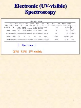
Multiobject Spectroscopy: Preparing and performing. Michael Balogh University of Durham. Outline. 1. Basic principles: What is MOS? 2. Pre-imaging: photometry and astrometry 3. Mask design 4. Carrying out observations at the telescope 5. Required calibration data. References. MOS (CFHT)

E N D
Multiobject Spectroscopy:Preparing and performing Michael Balogh University of Durham
Outline • 1. Basic principles: What is MOS? • 2. Pre-imaging: photometry and astrometry • 3. Mask design • 4. Carrying out observations at the telescope • 5. Required calibration data
References MOS (CFHT) Yee, Carlberg & Ellingson (1996; ApJS 102, 269) LDSS2 (Magellan) http://www.ociw.edu/magellan_lco/instruments/LDSS2/ldss2_maskgen.html GMOS (Gemini) http://www.gemini.edu/sciops/instruments/gmos/gmosMOS.html These lectures http://star-www.dur.ac.uk/~balogh/talks/OSIRIS/MOS_prep.html
Preimaging Need an image from which to design mask. Does not usually have to be from same telescope. • 1. photometric calibration • 2. astrometric calibration
Photometry • In principle, only relative photometry is required. • Exception may be alignment stars – need to ensure they are within required magnitude range • May need to take care that galaxy and stellar photometry are not on the same system!
Astrometry • This is the crucial step. Need accurate relative astrometry – take care of image distortions • Starlink astrom software has built-in geometrical corrections for Schmidt, astrographic, and AAT telescopes.
Astrometry • Transformation from [a,d] to CCD coordinates: • 1. Appropriate operations to transform to observed coordinates at observed epoch. • 2. Conventional gnomonic projection given chip centre, to obtain tangential coordinates [x,h] • 3. A cubic distortion correction: scale each of x,h by (1+q[x2+h2]) • q>0 : pincushion distortion • q<0 : barrel distortion • Can be specified, or fit directly from data (requires at least 10 stars)
1. First guess at plate solution. Overplot bright stars from USNO catalogue
3. Recentre and recompute mapping. Iterate until achieve ~0.1” accuracy
Mask design • Choose list of galaxy targets, astrometrically calibrated. Assign weights if desired • Choose at least 3 guide stars (preferably 4-5) - useful to overlap in dispersion direction • Specify length in spectral direction, if using blocking filter • Choose slit width, orientation, and minimum length
Differential Refraction 67° 20” Lewis et al. 2002
Differential Refraction 50° Point sources are stretched by ~4” at zenith angles of 67 degrees Minimize losses by putting slits at paralactic angle. Difficult unless you can guarantee the zenith angle! E-W slits minimize the effect at high airmass Take alignment image through same filter used for spectroscopy Lewis et al. 2002
Mask design • Allocate objects to masks. Determine conflicts given by (minimum) slit length and wavelength coverage. • Ensure full wavelength coverage obtained: requires slits to be near centre of mask in one dimension • Expand slit lengths to maximum allowed.
Preparation Dispersion direction • Choose galaxy priorities • Pick alignment stars so as to cause minimum disturbance to targets 2 2 1 5 3 3 2 3 3 2 4
1. Strict prioritisation Dispersion direction • Assign slits to highest priority objects first • Guarantees best targets will be observed • May not allocate the most slits possible 2 2 1 5 3 3 2 3 3 2 4 Allocates 4 galaxies
Expand slits? Dispersion direction • Assign slits to highest priority objects first • Guarantees best targets will be observed • May not allocate the most slits possible 2 2 1 5 3 3 2 3 3 2 4 Allocates 4 galaxies
2. Monte-Carlo Approach Dispersion direction • fTreat weights as a probability • Allows chance to increase number of slits • May choose low priority objects in favour of high 2 2 1 5 3 3 2 3 3 2 4 Allocates 7 galaxies
3. Optimize? Dispersion direction • Unsolved problem (Donnelly, Allen & Brodie 1992) • Need to assign a score, or cost function, which will depend on your science goals • How do you find the extremum of this function? 2 2 1 5 3 3 2 3 3 2 4 Allocates 7 galaxies
Mask design • Next: convert galaxy coordinates to x,y mask positions. Observer should not have to worry about this!
Mask cutting • Laser cutting preferred to machining, as it generally gives smoother slit edges (?) • Can be done in real-time, at the telescope. LAMA at CFHT is able to cut a mask in ~1 hour so that masks can be made as images are obtained.
At the telescope • 1. Target acquisition • 2. Align targets through same filter used for spectroscopy to minimize refraction effects • 3. Realign every ~hour to account for flexure/refraction shifts
Calibrations • 1. Arcs • 2. Flats • 3. Flux standards
Arcs • Take at same position to avoid flexure distortions (though this can be corrected using night-sky lines) • Ensure good coverage of full wavelength region of interest. May require using a filter with longer exposure
HeNeAr arc lamp (LDSS2) Red Blue Open filter Blue filter
Flats • Usually necessary for flux calibration. Useful for identifying slits and mapping distortion. • Must have dome flats, as sky flats will show features in the sky spectrum • Generally too noisy to be useful for taking out pixel-to-pixel variations • May be important if slits are not smooth (machine-cut)
Irregular slit


![Identification of Stereochemical Isomers of [Mo(CO) 4 (L) 2 ] by Infra-Red Spectroscopy](https://cdn2.slideserve.com/4500730/identification-of-stereochemical-isomers-of-mo-co-4-l-2-by-infra-red-spectroscopy-dt.jpg)