Download
1 / 29
290 likes | 430 Views
Environment Model Building Tool . MSE Presentation 1 Esteban Guillen. Outline . Project Overview Requirements Project Plan Cost Estimation Architecture Elaboration Plan SQA Plan Prototype Demo Questions. Project Overview. Goal

E N D
Environment Model Building Tool MSE Presentation 1 Esteban Guillen
Outline • Project Overview • Requirements • Project Plan • Cost Estimation • Architecture Elaboration Plan • SQA Plan • Prototype Demo • Questions
Project Overview • Goal • Provide a graphical tool to build and reuse 3D environment models for use in the CRS • Motivation • Improve on the original method of hard coding the environment model
Load XML file Save XML file Environment Simulator Environment Models (XML files) EMBT Initialize Environment Load XML file 3D Environment Display Project Overview Diagram
Build Environment Model • Description: This use case describes constructing the environment model from a 2D perspective. • Includes: Load Object(s), Load Terrain(s) • Pre-Conditions: There must be environment objects and environment terrains saved to disk. The user is in the environment model building mode. • Details: The user will build environment models from environment objects and environment terrains. The user will have a window, to draw environment objects and environment terrains, for building the environment model. The user will select either an object or terrain form a menu item and draw it on the window surface. Once the object or terrain has been drawn it can be resized, moved, and rotated with the use of the mouse. Each object and terrain will also have its own properties window that the user can pull up to modify attributes values for the object or terrain. The user will also be able to zoom in and out of the window. • Post-Conditions: An environment model is constructed and is ready to be saved.
Specific Requirements • SR1 [Critical Requirement] • The system shall provide a 2D graphical user interface to build environment models. • SR2 [Critical Requirement] • The system will allow the user to build environment models from environment objects and environment terrains. • SR3 • The system will allow the user to specify camera locations in the environment model. There will be a default camera with a top down view pointing a location (0,0,0). • SR4 • The system will allow the user to specify light source locations in the environment model. There will be a default light source to represent the sun. • SR5 • The system will provide a zoom-in and zoom-out feature for the environment model building graphical user interface.
Build Environment Terrain • Description: This use case describes building environment terrains from a 2D perspective. • Pre-Conditions: The user is in the environment terrain building mode. • Details: The user will be provided with a window to create the terrain. The window will initially have a flat surface. The user will be able to select regions of the surface and modify the elevation for the selected regions. Selecting a region will be done by drawing square or circular shapes with the mouse. Modifying the elevation will be controlled by mouse actions. The user will also be able to specify if the elevation change will be uniform over the selected area or if the center points increase faster, this will allow the user to make both smooth and rugged surfaces. A color coding will be used to provide visual feedback about the elevation changes. Black will represent the lowest elevations and white will represent the highest elevations. The user will be able to specify different levels of roughness for the surface of the terrain. The user will also be able to zoom in and out of the window. • Post-Conditions: When the user is done creating the terrain it is ready to be saved to disk.
Specific Requirements • SR6 [Critical Requirement] • The system shall provide a 2D graphical user interface to build environment terrains • SR7 • The system will allow the user to build environment terrains by selecting regions of an initially flat surface and then modifying the elevation. • SR8 [Critical Requirement] • The system will allow the user to save environment terrains to disk. • SR9 • The system shall provide a property window for each environment terrain. The property window will allow the user to modify the physical attributes of the environment terrain. • SR10 • Physical attributes for environment terrains will include color, dimensions, reflection properties, location, friction, and temperature. • SR11 • The system will provide a zoom-in and zoom-out feature for the environment terrain building graphical user interface.
Build Environment Object • Description: This use case describes building environment objects in a 2D perspective. • Pre-Conditions: The user is in the object building mode. • Details: The user will be provided with a window to create the object. Environment objects will be constructed from cube, cone, cylinder, and sphere primitive shapes. The user will draw primitive shapes on the window. Once the shapes are drawn on the window the user can resize, move, and rotate them with the mouse. Each primitive shape will have a properties window that the user can use to modify attribute values of the shape. The user will also be able to zoom in and out of the window. • Post-Conditions: When the user is done creating the new object it can be saved to disk.
Specific Requirements • SR12 [Critical Requirement] • The system shall provide a 2D graphical user interface to build environment objects. • SR13 [Critical Requirement] • The system will allow the user to build environment objects from the following Java 3D primitive shapes; Cones, Spheres, Cylinders, and Boxes. • SR14 [Critical Requirement] • The system will allow the user to save environment objects to disk. • SR15 • The system shall provide a property window for each environment object. The property windows will allow the user to modify the physical attributes of the environment object. • SR16 • Physical attributes for environment objects will include weight, color, dimensions, reflection properties, temperature, location, friction, and rotations. • SR17 • The system will allow the user to resize environment objects with the mouse. • SR18 • The system will allow the user to move the location of environment objects with the mouse. • SR19 • The system will provide a zoom-in and zoom-out feature for the environment object building graphical user interface.
View in 3D • Description: This use case describes viewing a model, object or terrain in 3D. • Pre-Conditions: There user must be in model building, object building or terrain building mode. • Details: The user will be provided with a window for viewing in 3D. The window will provide a 3D representation of the 2D building perspective. The user will be able to rotate the scene about the x, y, and z axis with mouse movements. The user will also be able to zoom in and out with mouse and keyboard actions. • Post-Conditions: None
Specific Requirements • SR20 • The system will allow the user to view environment objects from a 3D perspective. • SR21 • The system will allow the user to view environment terrains from a 3D perspective. • SR22 • The system will allow the user to view environment models from a 3D perspective. • SR23 • The system will allow the user to navigate through 3D perspectives with mouse movements.
Import/Export XML • Description: This use case describes exporting/importing XML representations of the environment model. • Pre-Conditions: There must be an environment model to export/import. • Details: There will be a menu item to either export or import the environment model. Both imported and exported files will be in XML format and will describe the objects and terrains included in the environment. When exporting an environment model the user will be provided with a window to name the XML file. When importing an environment model the user will be provided with a widow to select a XML file. • Post-Conditions: There will be a new file saved to disk if the user exports the model. If the user imports an environment model they will be in the model building mode (use case 1) after the file loads.
Specific Requirements • SR24 [Critical Requirement] • The system will allow the user to save the environment model to an XML format. • SR25 [Critical Requirement] • The system will be required to comply with a DTD for the XML file produced when saving the environment model. The Environment Simulator will determine the DTD specification. The DTD file will continually be evolving as the project progresses. A sample of the current DTD will be provided in the DTD Description Document. • SR26 • The system will allow the user to open and edit saved environment models.
Load Object (s) • Description: This use case describes loading environment objects into the environment model. • Pre-Conditions: There must be environment objects saved to disk. At a minimum the Java 3D primitive shapes (cone, box, sphere, and cylinder) will be provide. The user must be in environment building mode. • Details: The user will select environment objects from a menu. The user can then draw the environment object on the window provided by Use Case 1. • Post-Conditions: The object will be added to the environment model. • Specific Requirements: SR7 from use case 1.
Load Terrain (s) • Description: This use case describes loading environment terrains into the environment model. • Pre-Conditions: There must be environment terrains saved to disk. At a minimum a flat surface will be provided. The user must be in environment building mode. • Details: The user will select environment objects from a menu. The user can then draw the environment terrain on the window provided by Use Case 1. • Post-Conditions: The object will be added to the environment model. • Specific Requirements: SR7 from use case 1
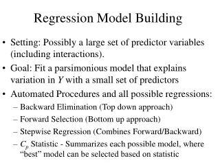
Cost Estimation • COCOMO model (organic) • Effort = 3.2*EAF (Size)^1.05 • Time (in months) = 2.5(Effort)^0.38
EAF • RELY as low and a value of 1.0. • DATA as high and a value of 1.1. • CPLX as normal and a value of 1.4 • TIME as normal and a value of 1.3 • STOR as low and a value of 1.1. • VIRT as low and a value of 0.95. • TURN as low and a value of 0.9. • ACAO as high and a value of 0.8. • AEXP as normal and a value of 1.0. • PCAP as normal and a value of 1.1. • VEXP as normal and a value of 1.0. • LEXP as high and a value of 1.0. • MODP as high and a value of 0.9. • TOOL as high and a value of 0.9 • SCED as high and a value of 1.15.
Calculations • KSLOC – 2500 (estimated from prototype and related examples) • Effort = 3.2*1.54*2.5^1.05 • = 12.9 staff months • Time = 2.5*12.9^0.38 • = 6.6 months
Architecture Elaboration Plan • Revision of Vision Document • Changes to the requirements or project scope since the first presentation must get updated in the vision document. • Revision of Project Plan • Changes to the schedule of the project must be updated in the project plan. The time and cost estimates will be revised using a bottom-up approach based on project progress. There will also be an Implementation Plan section added to the Project Plan document. • Architecture Design • The developer must have a strong understanding about how to build the system. All interfaces will be defined and UML diagrams will be used. • Development of Prototype • The prototype will demonstrate the critical requirements (defined in the Vision document) to demonstrate they can be implemented. • Test Plan • A test plan will document the tests that are to be performed to ensure the requirements are meet. • Formal Technical Inspections • The architecture design will be inspected by Cem Oguzhan and Kevin Sung. Both inspectors will produce a report on their inspection findings. • Formal Requirements Specification • At least one part of the project will be formally specified using a methodology such as OCL. I will formally specify some of the laws of physics for objects that are in the environment. For example objects should not be floating in mid air.
SQA Plan • References • Vision Document • Project Plan • IEEE Guide for Software Quality Assurance Planning • IEEE Standard for Software Quality Assurance Planning • Management • Organization • Supervisory Committee: • Dr. Scott DeLoach • Dr. David Gustafson • Dr. William Hsu • Major Professor: • Dr. Scott DeLoach • Developer: • Esteban Guillen • Formal Technical Inspectors: • Cem Oguzhan • Kevin Sung
SQA Plan • Tasks • All tasks to be performed have been documented in the project plan. A Gantt Chart is included in the project plan to provide a schedule for each task. • Documentation • All official documentation requirements for MSE students are defined at http://www.cis.ksu.edu/~sdeloach/mse/portfolio.html. The documentation will consist of a vision document, project plan, software quality assurance plan, action items, formal requirements specification, architecture design, test plan, formal technical inspection, prototype, user manual, component design, source code, assessment evaluation, project evaluation, references, formal technical inspection letters. All documentation will be reviewed by the committee members for final approval. • The all documentation will be posted on the developer’s web site at http://www.cis.ksu.edu/~ejg3500/embt. • Standards, Practices, Conventions, and Metrics • Documentation Standard – IEEE standards will be used as a guideline to follow. • Coding Standard – The project will use traditional object oriented analysis and design methods. Recommended Java style guidelines will also be followed. • Metrics – COCOMO will be used to estimate project effort. • Reviews and Audits • The committee members will be conducting reviews of the documentation as well as evaluating the developer at each presentation. The committee members will also comment on the software prototype demonstration to suggest changes and additions to the requirements. • Two technical inspectors will evaluate the architecture design artifacts and report on their findings.
SQA Plan • Test and Problem Reporting • All tests, along with their results, will be recorded on a time log web page. Unresolved problems will be reported directly to the committee members. • Tools, Techniques, and Methodologies • The following tools will be used for coding, testing, and documentation. • Eclipse IDE – for coding • Java 1.4.2 – for coding • Java 3D 1.3.1 – for coding • MS Visio – for documentation • USE 2.0.1 – for documentation and testing • JUnit 3.8.1 for unit testing • Code Control • The code will be controlled by a CVS system. The CVS is located at fingolfin.user.cis.ksu.edu/kdd/cvs.
SQA Plan • Deliverables • Phase I: • Vision Document • Project Plan • Demonstration • Software Quality Assurance Plan • Interface Definition • Phase II: • Action Items • Vision Document • Project Plan • Formal Requirements Specification • Architecture Design • Test Plan • Formal Technical Inspection • Executable Architecture Prototype
SQA cont. • Phase III: • Action Items • User Manual • Component Design • Source Code • Assessment Evaluation • Project Evaluation • References • Formal Technical Inspection Letters