Download
1 / 20
200 likes | 301 Views
Online Veto Analysis of TAMA300. Daisuke Tatsumi National Astronomical Observatory of Japan The TAMA Collaboration. 8 th GWDAW 19 Dec 2003 @ Milwaukee, UWM, USA. Introduction. <Veto Analysis> To distinguish GW signals from noises, we should identify the noise sources. .

E N D
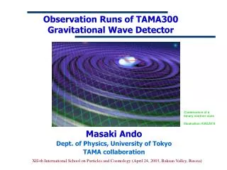
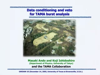
Online Veto Analysis of TAMA300 Daisuke Tatsumi National Astronomical Observatory of Japan The TAMA Collaboration 8th GWDAW 19 Dec 2003 @ Milwaukee, UWM, USA
Introduction <Veto Analysis> To distinguish GW signals from noises, we should identify the noise sources. In TAMA case, several noise contributions were already evaluated in the frequency domain as shown in this figure.
Introduction <Online Veto Analysis>Because detector conditions will be changed, we need to monitor all of noises continuously and in time.For example, a mean level of some noise do not contaminatethe displacement noise. But non-stationary noises may influence. Even in such case, if we monitor the noise contamination continuously, we can distinguish the noise from GW signals.For the veto analysis, it is very important to evaluate noise contamination continuously.
Checking of the noise contaminationmechanism • Online evaluation of these noise contaminations Contents • We began to study Veto Analysis intended to • the following noises: • Differential motion of Power Recycled Michelson (Hereafter it is called slm: small l minus) • Laser Intensity Noise(int) • By focusing on these, I talk about current status of
Noise Transfer Function = V4 / V2 WFer To confirm this model, we measured noise transfer function from slm to the displacement noise. Noise Contamination Mechanism(slm noise) UGF: 20Hz coupling constant Hslm H - - (llm) (slm) D Dslm A Aslm F Fslm WFslm V2 V4 This is a schematic view of noise contamination mechanism on slm. Slm is controlled at low frequency region below 20 Hz. In other words, at the observation band, it is not controlled. So we can consider that the noise contaminate via this path with a coupling constant of epsilon.
Noise Transfer Function(slm noise) Inconsistent with measurement. But the model is not consistent with measurement.
Compound mirror l2 Laser l1 l2 slm = l1 - l2 Laser l1 slm = l1 - l2 The origin of the difference Simple Power-Recycled Michelson This difference come from our incorrect assumption. We could not consider the slm to such a simple Power-Recycled Michelson. We should consider the slm to Power-Recycled Michelson with compound end mirrors. It means its reflectivity has frequency dependence.
H WFer Noise Contamination Mechanism(slm noise) UGF: 20Hz coupling constant Hslm H - - (llm) (slm) D Dslm A Aslm F Fslm WFslm V2 V4 We modified the model by taking into account such compound mirror effect as H.
Noise Transfer Function(slm noise) We confirmed that the modified model is consistent with measurement.
Noise Transfer Function = V4 / V3 WFer To confirm this model, we measured transfer function. Noise Contamination Mechanism(Intensity Noise) coupling constant UGF: 50kHz HINT H Intensity Noise - - (llm) (INT) D DINT A AINT F FINT DINT WFINT V4 V3 Next is intensity noise. It is also modeled in a similar way. But, because the intensity noise is controlled at observation band, only the suppressed intensity noise contaminate to the displacement noise with a coupling constant of epsilon.
Inconsistent with measurement. Noise Transfer Function(Intensity Noise) The amplitude is consistent, but the phase is not consistent.
Transfer Function (dT) The difference suggests us that this kind of all-path filter is necessary. But unfortunately we cannot understand why this filter is needed. Now numerical approach on this program is going on in our group.
dT WFer Noise Contamination Mechanism(Intensity Noise) coupling constant UGF: 50kHz HINT H Intensity Noise - - (llm) (INT) D DINT A AINT F FINT DINT WFINT V4 V3 Anyway we constructed model of noise contamination experimentally.
Noise Transfer Function (Intensity Noise) And we confirm the model is consistent with measurement.
Online evaluation of noise contamination Noise contamination mechanisms were modeled and were measured as transfer function. So we can evaluate noise contamination by using auxiliary noise spectrum. Moreover, in the online evaluation, coupling constants are also monitored by using calibration peaks to follow changing of the detector condition.
Calibration Peaks forNoise Calibration Intensity noise slm noise To monitor the coupling constant, sinusoidal wave signals were injected into each control system.
Noise Contamination(displacement L-, slm, Intensity) This figure shows displacement noise spectrum, black is total noise. And green and purple are slm and intensity noise contamination, respectively.
Noise Contamination(displacement L-, slm, Intensity) To enhance the Intensity Noise 1. Intensity Servo vary OFF 2. Add offset on l- Contamination of Intensity noise is well consistent with displacement noise
Summary To realize online veto analysis, 1. We check the noise contamination mechanisms of slm and intensity noises. 2. We demonstrate online evaluation of the noise contaminations. • In progress, • Increasing the number of monitored noise: • alignment, frequency noise and so on. • 2. Noise reduction by using this system.
Checking Transfer Function V3 / Vs HINT - DINT AINT FINT DINT WFINT Vs V3