Download
1 / 13
130 likes | 239 Views
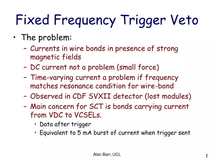
Fixed Frequency Trigger Veto. The problem: Currents in wire bonds in presence of strong magnetic fields DC current not a problem (small force) Time-varying current a problem if frequency matches resonance condition for wire-bond Observed in CDF SVXII detector (lost modules)

E N D
Fixed Frequency Trigger Veto • The problem: • Currents in wire bonds in presence of strong magnetic fields • DC current not a problem (small force) • Time-varying current a problem if frequency matches resonance condition for wire-bond • Observed in CDF SVXII detector (lost modules) • Main concern for SCT is bonds carrying current from VDC to VCSELs. • Data after trigger • Equivalent to 5 mA burst of current when trigger sent Alan Barr, UCL
Resonance condition doi:10.1016/j.nima.2004.08.120 • Finite element analysis and physical tests show narrow resonance peak near 18 kHz (55 us) for 3mm long bond wires with plane of wire bond perpendicular to Lorenz force (the unfavourable direction). • The actual wire bonds in the SCT will have lower amplitude and higher frequency resonances. • For detector safety the SCT will avoid running with fixed frequency triggers with frequencies above 15 kHz (but below 500kHz) • N.B. resonance is narrow so effect on physics running should be small (see later) Wire test FEA cdf-video Alan Barr, UCL
CentralTriggerProcessor Trigger sources L1A • In physics mode triggers come from the CTP LocalTriggerProcessor • In calibration mode triggers can/will come from other sources • LTP • TIM • ROD Externalsource BUSY • Trigger veto logic runs back up the chain TIM Externalsource ROD ROD ROD SCT DAQ crate Modules Alan Barr, UCL
ROD mode • Used in most calibration scans • Response curve, Noise occupancy, … • DSP code Master DSP controls trigger rate • Current implementation limits rate to < 15 kHz. • Good for detector safety • Does slow down calibration • Could allow faster triggers if pseudo-random • Not simple, but possible ROD ROD ROD Modules Alan Barr, UCL
TIM mode • TIM implements a Fixed Frequency Trigger Veto (FFTV) algorithm • Repetitive period monitoring • Count clocks between triggers • Store results • Check for period match • If match veto • Currently has several changeable parameters • Possible to modify e.g. matching criteria, veto time, over VME TIM Ext ROD ROD ROD Modules Alan Barr, UCL
Veto effect in TIM mode • TIM currently vetos fixed frequency triggers from either its internal generator or lemo sources when in calibration mode • Randomiser is used to produce triggers during TIM calibration scans • Tested with modules etc in SR1 • Application of veto generates warning for user Alan Barr, UCL
CentralTriggerProcessor Veto effect in LTP or CTP (physics) mode LocalTriggerProcessor • Same algorithm detects FFT • TIM asserts BUSY to LTP • LTP (or CTP) should stop sending triggers • What to do if it doesn't? BUSY TIM ROD ROD ROD Modules Alan Barr, UCL
Remaining risks 1/3 • TIM observes FFT but BUSY logic doesn't stop LTP/CTP from sending triggers • Solution: after a short (2μs) delay for busy signal propagation, TIM will go into “emergency” mode. Refuses to send triggers. • Clearance from this state requires manual intervention Alan Barr, UCL
Remaining risks 2/3 • Enthusiastic user disables trigger veto algorithm by changing registers and/or using jumper • Solution: parameters will be hard-wired into firmware. No way to change without reflashing TIM. • CAVEAT: Pixels! Firmware will detect hardware ID of board, • and if not an SCT board, will allow a jumper Veto. Alan Barr, UCL
Remaining risks 3/3 • Amateur ‘expert’ decides to send fixed frequency triggers directly from crate controller to ROD (not via MDSP histogramming code) • No way for ‘user’ to do this (at present) • More water-tight restriction required? • (The FFTV algorithm is quite small & might be able to be squeezed into the ROD local trigger firmware) Alan Barr, UCL
Bullet-proof TIM firmware • Will include solutions to remaining issues (1/3) and (2/3) above • Emergency mode • Hardwired parameters • Veto logic placed ‘last thing’ before triggers leave TIM • Can be ready by early March Alan Barr, UCL
Fixed Frequency Trigger Veto to CTP (RodBusy) Veto Disable/Inhibit Stand-alone Mode Local Emergency Action OK Frontpanel NIM Internal Trigger Generator Trigger Number Generator Frontpanel ECL Trigger-Out SA-Trig Trigger Run-Mode (TTC) TTC-Trig Trigger Number Decoder TTC Fibre “Bullet-proof” TIM firmware Alan Barr, UCL
Effect on Physics Running • Provided ATLAS L1A’s are not sent at fixed frequencies in the ‘danger zone’ then veto application will be very rare (less than about 1/day) • If triggers are send at fixed frequencies then we really do want to apply the veto more often! Place holder for veto rate plot Alan Barr, UCL