Download

1 / 22
220 likes | 311 Views
Explore a two-stage approach using IR redundancy removal and addition to optimize circuit timing for improved performance. The Greedy approach restructures the circuit by removing critical wires and adding stimuli to enhance timing efficiency. Examples demonstrate the selection process and critical path modifications. Discover how to use SIS for further speed-up and explore future developments in timing optimization.

E N D
Timing Optimization by IRredundancy Removal and Addition Speaker : Guo-Jhu Huang Advisor : Chun-Yao Wang 2009.08.14
Outline • Introduction • Our idea • Future work
Introduction • Timing optimization have been an important goal in IC design • Given a timing constraint (usually the clock period) • the combinational circuit must meet its timing constraint to work correctly
Introduction • In different phases, different techniques are used to improve circuit speed • Logic level: structure of circuit • Topological level: placement and routing • Physical level: sizing and buffering
Introduction • IRRA is a rewiring technique • Our goal is using IRRA to restructure the circuit for timing improvement
Our idea • First stage • Greedy approach • Second stage • Add stimulus to SIS, use sis timing engine to optimize the timing
Greedy approach • Define the timing model, • Gate delay = 1+ α.(# of fanout) original after removing the target wire • If choosing a dominator as a destination • gn.arrival_time <= gd.arrival_time • ga.slack > 0
Greedy approach original after removing the target wire • If choosing a forced MA as a destination • gn.arrival_time <= gd.required_time • ga.slack> 0
Greedy approach • 1. compute arrival, required and slack • 2. select candidate removed nodes • 3. choose candidate nodes’ fanin as wt to compute alternative wires • 4. choose the alternative wire with the largest weight • weight=number of removed critical wires • 5. add the alternative wire to remove many wires
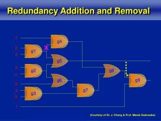
Example 1.Compute arrival time, required time and slack a:0.2 i1 r:2.0 g1 s:1.8 a:1.6 r:3.2 g5 a:0.2 o1 s:1.6 i2 a:4.2 r:1.8 r:4.2 g3 s:1.6 s:0 i3 a:3.2 a:0.4 r:3.2 r:0.4 g2 g6 s:0 s:0 o2 a:4.2 i4 a:1.8 a:0.2 r:4.2 r:1.8 r:0.4 s:0 g4 s:0 s:0.2 a:3.0 i5 r:3.2 a:0.2 s:0.2 r:2.0 s:1.8
Example 2. Select candidate removed nodes a:0.2 i1 r:2.0 g1 s:1.8 a:1.6 r:3.2 g5 a:0.2 o1 s:1.6 i2 a:4.2 r:1.8 r:4.2 g3 s:1.6 s:0 i3 a:3.2 a:0.4 r:3.2 r:0.4 g2 g6 s:0 s:0 o2 a:4.2 i4 a:1.8 a:0.2 r:4.2 r:1.8 r:0.4 s:0 g4 s:0 s:0.2 a:3.0 i5 r:3.2 a:0.2 s:0.2 r:2.0 s:1.8
Example 3. For each candidate nodes, choose its critical fanin as wt to compute alternative wires i1 g1 g5 o1 i2 wt g3 ga:g3 gd:g5 wt i3 wt wt g2 g6 o2 i4 g4 ga:i2 gd:i5 ga:g3 gd:i5 ga:g3 gd:g6 i5
Example • Greedy condition: • gn.arrival_time:1.6 <= original i5.required_time:2.0 • i2.slack:1.4 > 0 a:0.2 i1 r:1.8 g1 a:1.6 s:1.6 r:3.0 g5 o1 a:0.4 s:1.4 i2 a:4.0 r:1.8 r:4.0 g3 a:3.0 s:1.4 s:0 r:3.0 s:0 i3 a:0.4 wt g2 a:1.8 r:0.4 g6 a:4.0 s:0 r:1.8 o2 r:4.0 s:0 i4 a:0.2 s:0 r:0.4 g4 ga:i2 gd:i5 s:0.2 a:3.0 Original i5 gn r:3.0 a:0.2 a:0.2 a:1.6 s:0 r:2.0 r:0.6 r:1.8 s:1.8 s:0.4 s:0.2
Example i1 g1 g5 o1 i2 wt g3 gd:g5 ga:g3 wt i3 wt wt g2 g6 o2 i4 g4 gd:i5 ga:i2 gd:i5 ga:g3 gd:g6 ga:g3 i5
Example 4. Choose the alternative wire with largest weight target wire: g3-g6 alternative wire: gd:i5 ga:i2
SIS: Speed-up • 1. compute the slacks to find the critical nodes • 2. compute the weight of every critical node • weight=Wt+α*Wa • 3. use maxflow-mincut algorithm to find resynthesis cutset • 4. do partial collapse with depth d to resynthesis node • 5. decompose the resynthesis region
Stimulus to SIS • We take the resynthesis node as a dominator, and remove a wire to create a network
Stimulus to SIS • Which wire to remove? • The wire is on the critical paths • Weight=α.|slack|+β.Wn • 1) If the resynthesis node has D or D’ value • Wn=|P|, P={x| x is PI of SMA} • 2) If the resynthesis node has no value • Wn=Max(|P|, |Q|-|P|), Q={x| x is PI of gd and x is not PI of SMA}
Example Assume mincut node={g5,g6} g5 has no dominated critical wire to remove i1 g1 g5 o1 i2 g3 i3 g2 g6 o2 i4 g4 i5
Example Assume mincut node={g5,g6} i1 g1 g5 o1 i2 g3 i3 g2 g6 o2 i4 g6 has no dominated critical wire to remove g4 i5
Future work • Find some ideas to improve • Programming