Download
1 / 15
160 likes | 310 Views
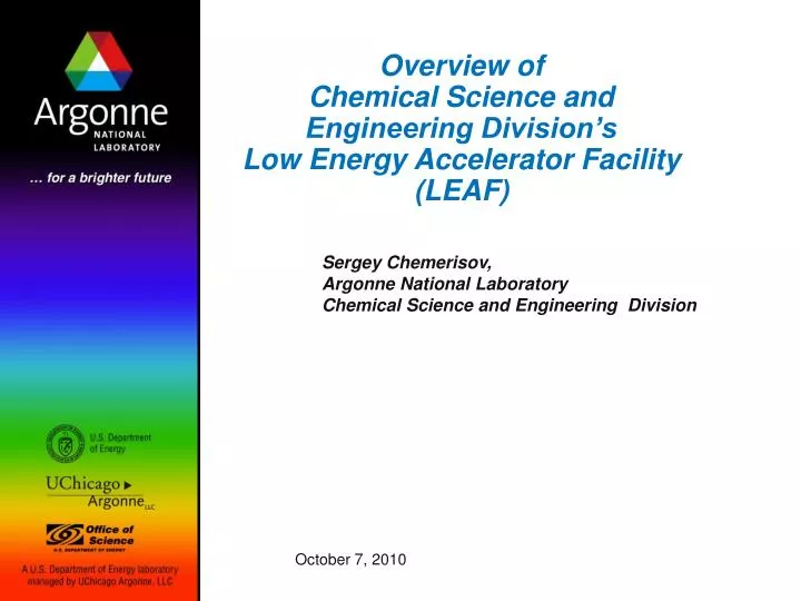
Overview of Chemical Science and Engineering Division’s Low Energy Accelerator Facility (LEAF). Sergey Chemerisov, Argonne National Laboratory Chemical Science and Engineering Division. October 7, 2010. LEAF facility at Argonne. LEAF facility.

E N D
Overview of Chemical Science and Engineering Division’sLow Energy Accelerator Facility (LEAF) Sergey Chemerisov, Argonne National Laboratory Chemical Science and Engineering Division October 7, 2010
LEAF facility at Argonne LEAF facility
Building 211 Low energy Accelerator Facility Service Floor Unexcavated A-004 E-010 Unexcavated E-001 E-024 A-011 A-053 Chemistry Division 3 MEV E-036 Van De Graaff A-035 Unexcavated E-034 A-056 Unexcavated A-051 Spec Room B-001 D-032 Scale 1 inch = 10 feet D-024 E-031 C-001 B-012 E-040 Unexcavated Unexcavated Unexcavated Cyclotron Vault D-035 D-001 D-017 LINAC Unexcavated Cell E-049 Unexcavated Instrument Room D-070 E-046 D-076 D-072 Unexcavated Unexcavated Unexcavated Cell 2 Unexcavated Unexcavated Unexcavated Unexcavated Setting of the LEAF 20 MeV electron linac 3 MeV Van de Graaff Instrument Room LINAC Pit
3 MeV Van de Graaff accelerator facility Electron beam • e- energy 1-3 MeV • Pulse width 5, 12, 25, 55, 100 ns, 1s - 1 ms or DC • Pulse rise time in nano second mode ~ 3 ns • Maximum electron current 500 A (administratively limited to 100 A) • Pulsed current 2A (up to 5A with reduced cathode lifetime) • Beam size 5 mm can be focused down to 1 mm spot • Energy stability ~1% Positive ion beam H+ or D+ • energy 1-3 MeV • Maximum current 500 A • DC only
Chemistry Division 3 MEV E-036 Van De Graaff E-034 E-040 E-049 Instrument Room E-046 3 MeV Van de Graaff accelerator
General description • L – band, 1.3 GHz • Energy 2-22 MeV • 2 accelerating structures (11 cavities, 11.83 MeV per structure unloaded) • 2 klystrons (20 MW peak, 50 KW average) • 0.0025 klystron duty factor • Pulse width 30 ps - 5 ms • 2.5 A peak current in steady state mode • 1000 A peak current in 30 ps pulse
Beam Characteristics • Steady state mode Pulse width 0.5 - 5 ms (train of 30 ps pulses separated by 770 ps) Repetition rate 60 Hz (100 Hz power supply limited) Peak current up to 2.5A at 14 MeV Beam size ~1 cm • Average current: 2.5 A x 0.0025 (klystron duty factor)=6.25 mA PFN line is limited to 300Hz and 5 ms • Pico second (single pulse) mode: 30 ps single pulse High peak intensity achieved by compressing 4 ns pulse with 1/12 sub harmonic buncher • Nano second mode: 4, 6, 8, 10, 20, 40, 80, 100 ns pulses
20 MeV Linac Instrument Room Spec Room D-032 D-024 D-035 D-001 D-017 LINAC Pit LINAC Cell D-070 D-076 D-072 Cell 2 CHEMISTRY LEAF ASRC REVIEW November 29, 2005
Plans for linac upgrade Driver: Medical isotope production. Step 1. Already implemented Power upgrade: increase repetition rate to 270 Hz to achieve 40 kW total power in the beam Step 2. Completion planned for June 2011 Beam energy upgrade: Increase beam energy to 58 MeV an keeping all other machine parameters same
Present condition of positron production line at Chemistry division linac Front end bends to separate electrons from positrons shielding Output end detector