Download
1 / 8
90 likes | 196 Views
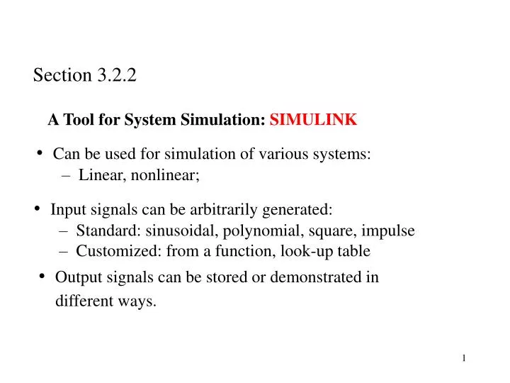
Section 3.2.2. A Tool for System Simulation: SIMULINK. Can be used for simulation of various systems: Linear, nonlinear;. Input signals can be arbitrarily generated: Standard: sinusoidal, polynomial, square, impulse Customized: from a function, look-up table.

E N D
Section 3.2.2 A Tool for System Simulation: SIMULINK • Can be used for simulation of various systems: • Linear, nonlinear; • Input signals can be arbitrarily generated: • Standard: sinusoidal, polynomial, square, impulse • Customized: from a function, look-up table • Output signals can be stored or demonstrated in • different ways.
Example: Input u Click simulation and use plot(t,y), you will get a time response of y • The parameters can be easily changed; • The initial condition can be easily changed.
The components: • Main components with dynamics: • integrators, • transfer function • zero-pole description • The first one needs an initial condition. • It can be assigned by clicking on the • component • Math components: • gain (amplifier) kx : x a scalar • addition (a+b+c); product (ab); you can change the number of terms and the sign of each term
Sources: input signals • constant, step, ramp • pulse, sine wave, square wave • from data file • signal generator • The clock to record time • Sinks: for output demonstration or storage • export to workspace; you can give a name to the variable, such as u, y, x, etc. • scope • digital display
Example: Find the solution to the systems where y(0)=0; y’(0)=0. u(t) is a square wave. • Steps: • Open matlab workspace • type simulink and return • - simulink library browser window is open • Click file and choose new then choose model • - a blank window is open • Open one of the commonly used blocks and drag and drop • whatever you need to the blank window. • 5. Connect the components by arrows.
Click each component to setup the parameters properly • sinks labeled “t”, “u”, “y”: choose “array” for save format • sampling time can be a parameter inputted from workspace • they can be chosen as -1 for inherited • When ready, click simulation and choose configuration parameters • to setup simulation time. Finally, click simulation and choose start • When finished, type plot(t,y,t,u) to plot the input and output
How to realize and then realize Can we first get Theoretically, we need future information of u(t), t > t0 to get the derivative at t0. This cannot be realized. We may only use the past information to get an approximation. But still it is better not to use differentiator. If a signal is contaminated by noises, taking derivative will magnify the noises. One approach to avoid differentiation is as follows: - First realize Initial condition determined from Then set -You can verify that y satisfies (*).
- -