Download
1 / 80
800 likes | 1.03k Views
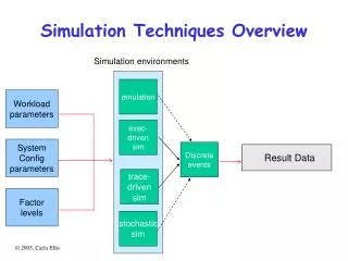
ASTICE. Advanced Simulation Techniques for IC Engines. CFD- 3D general flow analysis. Application. Engine Cycle Simulation. Engine Cycle Simulation-Case 1. Weibe combustion model. Engine Cycle Simulation-Case 1. Single DI Weibe. Start of combustion Crank angle at 1% burned.

E N D
ASTICE Advanced Simulation Techniques for IC Engines
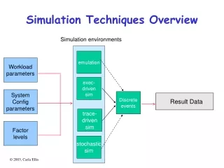
CFD- 3D general flow analysis Application
Engine Cycle Simulation-Case 1 Weibe combustion model
Engine Cycle Simulation-Case 1 Single DI Weibe Start of combustion Crank angle at 1% burned Weibe combustion model Fit Weibe function to experimental or CFD heat release • Combustion Duration & Weibe exponent • Calculated by non-linear least square method Start of combustion Crank angle at 0.5% burned Multiple DI Weibe • Premixed fraction, Premixed combustion duration , premixed Weibe exponent, mixing controlled combustion duration and mixing controlled Weibe exponent • Calculated by non-linear least square method
Engine Cycle Simulation-Case 1 Single Weibe Model SOC = -5.3 Θd= 63.5 M = 0.96 Multiple Weibe Model SOC = -4.1 Pf = 0.1 Θd_p= 12 Mp = 0.5 Θd_p= 60 Mp = 1.15
Engine Cycle Simulation-Case 1 Single Cylinder results Zoom
Engine Cycle Simulation-Case 1 Single Cylinder results Scavenging
Engine Cycle Simulation-Case 1 Single Cylinder results Fuel Energy 196.8 kW
Engine Cycle Simulation-Case 1 Single Cylinder Model Firing Order/ No. Cylinders TC and IC model Filling & Emptying Model Friction Model
Engine Cycle Simulation-Case 1 Filling & Emptying Model
Engine Cycle Simulation-Case 1 Gas Exchange Diagram Filling & Emptying Results
Engine Cycle Simulation-Case 1 Filling & Emptying Model Results Compressor Raw Map Turbine Raw Map
Engine Cycle Simulation-Case 2 Multi-zone spray Model for Diesel combustion More info: SAE paper No. 2001-01-1246
Engine Cycle Simulation-Case 2 Multi-zone spray Model for Diesel combustion
Engine Cycle Simulation-Case 2 Multi-zone spray Model for Diesel combustion Start of Combustion Premixed combustion Temperature Distribution in Spray Zones
Engine Cycle Simulation-Case 2 Multi-zone spray Model for Diesel combustion Combustion tale Peak heat release rate Temperature Distribution in Spray Zones
Engine Cycle Simulation-Case 2 Multi-zone spray Model for Diesel combustion NOx & SOOT Fuel evaporation & Burn
Engine Cycle Simulation-Case 2 Multi-zone spray Model for Diesel combustion Pressure & Temperature NormalizedFuel Injection, Evaporation, Burn and Heat release rate
Engine Cycle Simulation-Case 3 Two-Zone knock model for SI and DF engine
Engine Cycle Simulation-Case 3 Two-Zone knock model for SI and DF engine The Unburned Zone The Burned Zone CO CO H2O H2O CHO O CH4 O2 HO2 O2 CO2 N2 OH H2O2 CH3 OH N2 H H H2 CH2O Chemical Kinetics Thermodynamic Equilibrium Auto-ignition Knock Heat Release
Engine Cycle Simulation-Case 3 Two-Zone knock model for SI and DF engine
Engine Cycle Simulation-Case 3 Two-Zone knock model for SI and DF engine Model Validation Continuous lines : Two-Zone model results Points : CAT Engine simulation results (SAE paper)
Engine Cycle Simulation- Case 4 • 1D gas dynamic model 1D CFD Complex program Better Results Filling & Emptying Modeling
Engine Cycle Simulation- Case 4 • 1D gas dynamic model Two-Step lax-Wendroff method Flow Limit Function
Engine Cycle Simulation- Case 4 1D gas dynamic model
Engine Cycle Simulation- Case 5 • Turbocharger Matching Criteria for turbo matching
Engine Cycle Simulation- Case 5 • Turbocharger Matching/ Transient operation Load Increase Process
Engine Cycle Simulation- Case 5 • Turbocharger Matching/ Transient operation 150 Sec Ramp of Throttle from 0-100-Transient Response
Engine Cycle Simulation- Case 5 • Turbocharger Matching/ Transient operation 150 Sec Ramp of Throttle from 0-100-Transient Response
Engine Cycle Simulation- Case 5 • Turbocharger Matching/ Transient operation 40 Sec Ramp of Throttle from 0-100-Transient Response
Engine Cycle Simulation- Case 5 • Turbocharger Matching/ Transient operation 40 Sec Ramp of Throttle from 0-100-Transient Response
Engine Cycle Simulation- Case 5 • Turbocharger Matching/ Transient operation 12 Sec Ramp of Throttle from 0-100-Transient Response
Engine Cycle Simulation- Case 5 • Turbocharger Matching/ Transient operation 12 Sec Ramp of Throttle from 0-100-Transient Response
Optimization Process RSM Methodology
Optimization Model- DOE Methods Increase in Run time Increase in Level of Accuracy
Optimization Example 1 Injection timing VS Speed & fuel amount Response Surfaces
Optimization Example 1 Injection timing VS Speed & fuel amount Optimized Map
Cooling circuit simulation-Case 1 • Simple and Extended model of Heat exchanger Simple Model
Cooling circuit simulation-Case 1 • Simple and Extended model of Heat exchanger Extended Model
Cooling circuit simulation-Case 1 • Simple and Extended model of Heat exchanger
Cooling circuit simulation-Case 2 • Coupled Solution with Engine Cycle Simulation/ Transient/ Extended pump model Heat transfer BCs Heat Rejection
Cooling circuit simulation-Case 2 • Coupled Solution with Engine Cycle Simulation/ Transient/ Extended pump model Transient Operation of the engine
Cooling circuit simulation-Case 2 • Coupled Solution with Engine Cycle Simulation/ Transient/ Extended pump model Transient Operation of the engine