Download
1 / 23
230 likes | 320 Views
Welcome to 3D . The 3D graphics pipeline Rigid-body transform Homogeneous coordinates Viewing transformation Projection Illumination. Rasterization & Clipping & Display . Illumination. Projection . . L. N. . 1 R. . 1 V. Basic Rendering Pipeline. ViewingTransformation

E N D
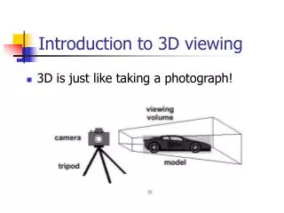
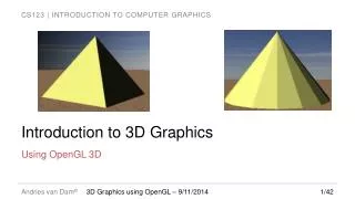
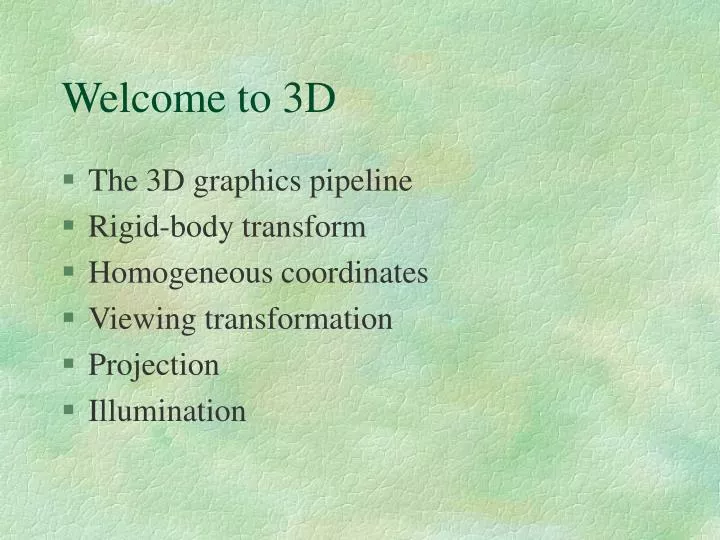
Welcome to 3D • The 3D graphics pipeline • Rigid-body transform • Homogeneous coordinates • Viewing transformation • Projection • Illumination
Rasterization & Clipping& Display Illumination Projection L N 1R 1V Basic Rendering Pipeline ViewingTransformation (WS -> CS) Modeling Transformation (OS -> WS) Visibility Culling Database of 3D models
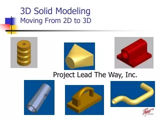
Modeling Transformation ViewingTransformation (WS -> CS) Visibility Culling Illumination Projection Rasterization & Clipping & Display Modeling Transformation (OS -> WS) Database of 3D models • 3D models defined in their own model space or object space(OS) • Modeling transformations orient models within a common coordinate system called world space (WS) • All objects, lights, and camera (viewer) is in one world space
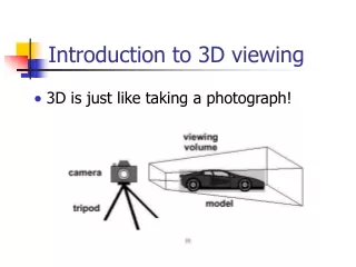
Viewing Transformation ViewingTransformation (WS -> CS) Visibility Culling Illumination Projection Rasterization & Clipping & Display Modeling Transformation (OS -> WS) • Another change of coordinate systems • Maps points from world space into eye (camera) space • Eye position becomes the origin and viewing direction is oriented along some axis (z/-z) eye World space
Visibility Culling ViewingTransformation (WS -> CS) Visibility Culling Illumination Projection Rasterization & Clipping & Display Modeling Transformation (OS -> WS) Database of 3D models • Viewing volume is defined. Objects outside viewing volume is not visible. • This process can contribute substantial performance improvement and there are many number of techniques.
L N 1R 1V Illumination ViewingTransformation (WS -> CS) Visibility Culling Illumination Projection Rasterization & Clipping & Display Modeling Transformation (OS -> WS) • Illumination needs to be done before projection since Z value does matter for shading calculation • Shading usually refers local illumination calculated based on surface material, surface normal, view direction, and light source • Texture map can be added here • Global illumination adds interaction between objects, reflection, refration, BRDF, etc
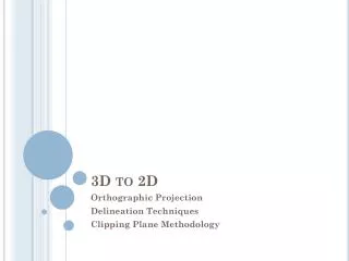
Projection ViewingTransformation (WS -> CS) Visibility Culling Illumination Projection Rasterization & Clipping & Display Modeling Transformation (OS -> WS) •Another transformation from camera space to image space
Projection ViewingTransformation (WS -> CS) Visibility Culling Illumination Projection Rasterization & Clipping & Display Modeling Transformation (OS -> WS) •Another transformation from camera space to image space • Z value is used to calculate ratio of x & y and then discarded (right after Z buffer comparison)
Rasterization, Clipping, Display ViewingTransformation (WS -> CS) Visibility Culling Illumination Projection Rasterization & Clipping & Display Modeling Transformation (OS -> WS) • Final transformation from image space to viewport coordinates • Filling pixels • Z buffer (Closer objects over write farther objects) • Clipping cuts off objects outside of viewport • 2D operation (filling a triangle properly)
Rigid-Body Transformation • Euclidean transformation • Preserve the shape of the objects that they act on • Includes rotations and translations rotation translation
Homogeneous Coordinate System • Rotation multiplies and translation adds • causes distingtion for every single calculation • Homogeneous system treats translation and rotation same by extending one dimension • Repeating usages, scale, skew are also fine
Viewing transformation • Same with other transformation (rotation + translation) • Specially treated because camera position + viewing direction defines it. eye
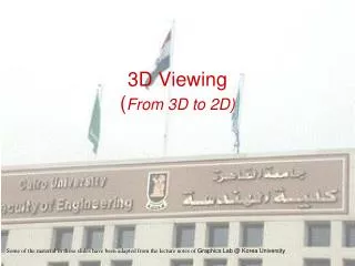
(Perspective) Projection • The projection maps all of out 3D coordinates onto our desired viewing plane, thus making 3D world into an image
L N 1R 1V Shading • A reflection (diffuse + specular + florescence) model describes the interaction of light with a surface, in terms of the properties of the surface and the nature of the incident light. • Surface : surface normal + material (combination ofka, kd, ks and n) • I = Iaka + Ii[kd(L•N) + ks (R•V)n]/(r+k)
Global Illumination • Local shading (Gauroud shading, Phong shading) does not calculate global effect (shadow, reflection, refraction, scattering, etc) • Ray tracing • Radiosity • Combination of both
Texture (map) • Blinn, 1978 • Texture mapping is the process of transforming a texture onto the surface of a three-dimensional object. • Makes object realistic appearance, but increasing the overall size of object (problem when transmitted) • Bump mapping
Other issues • Rendering acceleration (rasterization, texture map, spacial subdivision, collision detection, progressive rendering, view dependent rendering, image-based rendering,…) • Anti-aliasing • Physically based simulation
Project 1 • Your first project is (1) to make you feel comfortable with VRML world. Build your (static) VRML world. You may import 3D models from other tool, but you should have full control over the model to make use of them in your project 2. This project is also (2) to make your base environment for project 2 (multi user game). Therefore, think carefully in advance, not to waste your time and do it again for project 2. Your project 2 should have some component that multi users interact in 3D world. For example, car racing game needs cars and tracks at least. Shooting game needs 3D avatars and shooting environment. You build at least a car and tracks that you want to use for racing game. For project 1, your world can be static, no need to animate, respond to user input, nor events handling. Build your static world in .wrl file and test in your browser. For project 2, you will have to work towards installing (or implementing) server, EAI scripting of your VRML components using java (this also requires game algorithm – collision, running speed, etc).
Grading : Grading of project I will be based on your world and documentation. Your world needs to have textured and navigatable environment, with multiple light sources. If your world looks reasonable enough for project 2, then you will get most of credit. For documentation, draw scene graph at least. Also use this documentation as a proposal for your project 2 since you will have to spend some time to design project 2 anyway. • Submission : Hard copy of documentation that obviously includes URL of your world by 4:00 pm of 10/8/2001.
An Overview of VRML • Scene Graph Structure VRML files describe 3D objects and worlds using a hierarchical scene graph. Entities in the scene graph are called nodes. VRML 2.0 defines 54 different node types, including geometry primitives, appearance properties, sound and sound properties, and various types of grouping nodes. Nodes store their data in fields, and VRML 2.0 defines 20 different types of fields that can be used to store everything from a single number (the SFFloat field type) to an array of 3D rotations (the MFRotation field type). • Event Architecture VRML 2.0 defines an event or message-passing mechanism by which nodes in the scene graph can communicate with each other. Each node type defines the names and types of events that instances of that type may generate or receive, and ROUTE statements define event paths between event generators and receivers. • Sensors are the basic user interaction and animation primitives of VRML. The TimeSensor node generates events as time passes and is the basis for all animated behaviors. Other sensors are the basis for all user interaction, generating events as the viewer moves through the world or when the user interacts with some input device. Sensors only generate events; they must be combined with other nodes via ROUTE statements to have any visible effect on the scene.
Scriptnodes can be inserted between event generators (typically sensor nodes) and event receivers. Scripts allow the world creator to define arbitrary behaviors, defined in any supported scripting language. The VRML 2.0 specification defines Script node bindings for the Java and JavaScript languages. • Interpolator nodes are essentially built-in scripts that perform simple animation calculations. They are usually combined with a TimeSensor and some node in the scene graph to make objects move. • Prototyping: Encapsulation and ReuseVRML 2.0 includes a prototyping mechanism for encapsulating and reusing a scene graph (the PROTO statement). Geometry, properties, and animations or behaviors can be encapsulated, either separately or together. Prototyping allows the definition of a new node type in terms of a combination of existing node types, which can make VRML easier to use and can reduce the size of VRML files. • Distributed Scenes VRML 2.0 includes two primitives that allow a single VRML world definition to span the WWW. The Inline node allows the inclusion of another VRML file stored anywhere on the Web and the EXTERNPROTO statement allows new node definitions to be fetched from anywhere on the WWW. More generally, EXTERNPROTO allows nodes to be defined external to the VRML file and it is the basic extensibility mechanism for VRML.
VRML + HTML + Java • VRML file inside an HTML file: This is a semistandard part of HTML using the <EMBED> or <OBJECT> HTML tag, although HTML does not require that HTML browsers support embedding of VRML files (or any other type of file) into HTML documents. • Java code inside a VRML file: This is a standard (although not required) part of VRML 2.0, using a Script node that refers to the compiled Java code. • Java applet communicating with a VRML browser: This is a not-yet-standard extension to VRML 2.0 known as the External Authoring Interface (EAI). At some time in the future it will probably become a standard (but perhaps not required) part of VRML.
Java classes corresponding to VRML nodes: Several companies are developing programming toolkits that define in-memory representations of VRML nodes that can be used in any way the programmer wishes. These can be extremely useful when implementing VRML browsers or VRML tools, but none are yet a standard part of either VRML or Java. • HTML file inside a VRML file: Using an HTML file as a texture map to display it inside a 3D world would be an interesting extension to VRML, but it is not yet supported by any VRML browser and is not part of VRML 2.0. • Java applet inside a VRML file: Using a Java applet as a texture map to display the Java program inside the 3D world would also be an interesting extension. Interaction with the Java program could also be supported by projecting pointing device motion onto the applet. However, this also is not supported and is not part of VRML 2.0.