Download
1 / 12
120 likes | 405 Views
Si-strip STS: Layout. Valeri Saveliev, Obninsk State University 7-10-2001. CBM Collaboration Meeting. New Geometry of the Si-Strip STS 4 Si-Strip Planes inside the Magnet ( equivalent distances along z ). Significant Reducing the Requirements for the Si-Strip STS Design

E N D
Si-strip STS: Layout Valeri Saveliev, Obninsk State University 7-10-2001 CBM Collaboration Meeting
New Geometry of the Si-Strip STS 4 Si-Strip Planes inside the Magnet ( equivalent distances along z ) Significant Reducing the Requirements for the Si-Strip STS Design ( STS_3 is MAPS technology ) New Si-Strip STS Geometry STS_7 STS_6 STS_5 STS_4 z 100 cm 80 cm y 60 cm x 40 cm
Geant 4 view of Si-Strip STS Geometry Main factors taking to account for Si-Strip STS Layout : • Occupancy • Resolutions for x & y • Fake rate production Si-strip STS Geometry
Total Occupancy of Si-Strip STS STS_4, STS_5, STS_6, STS_7 (Total Number of Points on the Planes ) 100 Au+Au 25 GeV/A events Occupancy of Si-Strip STS STS_4 STS_5 STS_6 STS_7
Occupancy of Si-Strip STS STS_4, STS_5, STS_6, STS_7 ( 1 cm of Central Parts along X in Modules ) 100 Au+Au 25 GeV/A events Occupancy of Si-Strip STS
Keep the Point Resolution on the Level: 50 mkm Resolution of Si-Strip STS y s_x X 900 450 150 s_y = const ( 8 mkm )
Fake Rate Fake Rate of Si-Strip STS
Double Sided Si-Strip Detectors Thickness : 100 mkm Pitch of strips : 25 mkm Stereo Angle : 15o Inner region of Si-Strip STS: 25 mkm Pitch gives 400 strips per cm According the occupancy plots for STS_4: 10 Point per cm per event, or 2.5 % for 1 cm length strip 17 Point per cm per event, or 4.2% for 2 cm length of strip Basic Technology of Si-strip STS
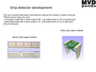
Outer region of the Si-Strip STS: Long Lader Technology ( SiLC Collaboration) Basic Technology of Si-strip STS Sensors are 4’’ , 300 µ thick, double-sided, 70 × 40.1 mm2, 110 µ/208µ readout pitch (p: junction side/n: ohmic side). A set of strips are connected in serpentine; thus strips with following length: 28 cm, 56 cm, 112 cm and 224 cm are tested.
Basic Elements: Inner : 6x2 cm Middle : 6x4 cm Outer : 6X12 cm Si strip STS_4 Layout +20 cm -20 cm Read out
Basic Elements: Inner : 6x4 cm Middle : 6x12 cm Outer : 6X20 cm Si strip STS_6 Layout +40 cm +4cm - 4cm -40 cm Read out
Plans • Implementation in to MC: • New Geometry • Layout of the Si-Strip STS • Definition of the Hits Structure Test with the Reconstruction