Download

1 / 12
130 likes | 476 Views
Mechanical Engineering Drawing and Graphics (ME 210). Term 041 Course Outline & Introduction. Instructor Details. Mohammed Faisal Ahmed Office: Room 23/059 Phone: 2797 E-mail: faisal@kfupm.edu.sa URL http://faculty.kfupm.edu.sa/me/faisal OH: SUM – 10:00 - 10:50 am

E N D
Mechanical Engineering Drawing and Graphics (ME 210) Term 041 Course Outline & Introduction
Instructor Details Mohammed Faisal Ahmed Office: Room 23/059 Phone: 2797 E-mail: faisal@kfupm.edu.sa URL http://faculty.kfupm.edu.sa/me/faisal OH: SUM – 10:00 - 10:50 am T – 11:00 – 11:50 am Courses added to WebCT
Course Outline Outline
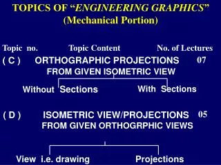
The Graphic Language & Design • The members of the engineering design project team must be able to communicate among themselves and with the rest of the project team in order to contribute to the team’s success. • The graphic language is the universal language used by every engineering team designing and developing products throughout the world. • There are two basic types of drawings: artistic and technical. • Technical drawing is based on the universal principles of descriptive geometry, developed in the late eighteenth century in France.
The Graphic Language & Design • The design process is the ability to combine ideas, scientific principles, resources, and existing products into a solution for a problem. It consists of five specific stages. • Problem Identification • Concepts & Ideas • Compromise Solutions • Models or Prototypes • Production or working drawings
Introduction to CAD • Computers have revolutionized the drawing process. New technologies are constantly invented which make this process quicker, more versatile, and more powerful. • CAD is the tool of choice for engineering design companies. The effective user of this tool requires an understanding of technical drawing fundamentals as well as training on the CAD software program.
Introduction to CAD • CAD software can draw in three dimensions (width, height, and depth), unlike paper drawing which only consists of two dimensions in a single view. • Different CAD packages have different operational procedures, and different strengths and weaknesses. Three features found in all CAD software are commands for geometry generators, functions to control the viewing of drawing geometry, and modifiers for changing the drawing or editing variations. • Operating a CAD system typically has required extensive training. Newer CAD systems are becoming more user friendly, but one should not overestimate the claims CAD packages make. It is important to evaluate each package thoroughly and make an informed decision.
Instrument Drawing, Freehand Sketching & Lettering Techniques • An understanding of the basic principles of drawing is required to draw with either a pencil or with CAD software. • Both CAD and traditional drawing have specific methods for drawing lines, arcs, and circles. Proper understanding of the elements of this basic geometry is essential for both mechanical and CAD drawing. • Every drawing tool, including every CAD software program, requires careful study of the tools and procedures for using the tools. Proper use of each tool facilitates the creation of neat, accurate drawings. Improper use of a tool creates sloppy, inaccurate drawings. • The proper sizing of a drawing requires complete understanding of the use of scales. Paper drawings are scaled before they are drawn. CAD drawings are scaled when they are printed.
SolidWorks Introduction
Introduction • It is a state-of-the-art 3D CAD modeling tool • It represents an object in a virtual environment just as it exists in reality, i.e. having mass and volume properties as well as surfaces and edges • Complex 3D parts with contoured surfaces and detailed features can be modeled quickly and easily • Many parts can be assembled in a virtual environment to create a computer model of the finished product (assembly) • Traditional engineering drawings can be easily generated from the solids models of both the parts and the final assembly
Constraint Based Solid Modeling • The 3D Modeling begins with the creation of a 2-D sketch of the profile for the cross section of the part. • The initial sketch need not be accurate; it needs only to reflect the basic geometry of the part’s cross-sectional shape. Details of the cross-section can be added later. • The next step is to constrain the 2-D sketch by adding enough dimensions and parameters (defining relations) to completely define the shape and size of the 2-D profile. • Finally, a three-dimensional object is created by revolving, sweeping or extruding the 2-D sketched profile. EXAMPLE
SolidWorks Demo DEMO