Download
1 / 27
280 likes | 300 Views
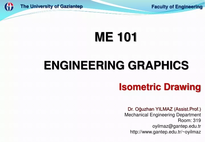
The University of Gaziantep. Faculty of Engineering. ME 101 ENGINEERING GRAPHICS Dr. Oğuzhan YILMAZ ( Assist.Prof. ) Mechanical Engineering Department Room: 319 oyilmaz@gantep.edu.tr http://www.gantep.edu.tr/~oyilmaz. Isometric Drawing. Isometric Drawing. ME 101.

E N D
The University of Gaziantep Faculty of Engineering ME 101 ENGINEERING GRAPHICS Dr. Oğuzhan YILMAZ (Assist.Prof.) Mechanical Engineering Department Room: 319 oyilmaz@gantep.edu.tr http://www.gantep.edu.tr/~oyilmaz Isometric Drawing
Isometric Drawing ME 101 Introductionand Objectives • This lecture introduces the concept of Isometric projection and Isometric drawing of an object. • Followings will be highlighted to be able to explain the Isometric drawing: • Axonometric projection • Isometric projection • Isometric drawing • Isometric and non-isometric lines (Boxing and offset methods) • Angles in isometric drawing • Curves in isometric drawing • Circles in isometric drawing (Four center ellipse) • Isometric circle arcs • Students are required to understand the fundamentals of isometric drawing and the technical and practical details while drawing of an object. Dr. Oğuzhan Yılmaz
Isometric Drawing Parallel & normal to picture plane B A D C B Line of sight A D C ME 101 Axonometric Projection • Is a parallel projection technique used to create a pictorial drawing of an object by rotating the object on an axis relative a projection or picture plane. • Axonometric projection is one of the four principalprojection techniques: multiview, axonometric,oblique and perspective Dr. Oğuzhan Yılmaz
Isometric Drawing ME 101 Axonometric Projection • InMulti views and axonometric projections,the • lines of sight are perpendicular to the plane of projection;therefore, both are considered orthographic projections Dr. Oğuzhan Yılmaz
Isometric Drawing a b c B A a D c C b B a A c b D C ME 101 Axonometric Projection Type of axonometric drawing Axonometric axis 1. Isometric All angles are equal. Axonometric axis Two angles are equal. 2. Dimetric Axonometric axis None of angles are equal. 3. Trimetric Dr. Oğuzhan Yılmaz
Isometric Drawing ME 101 Isometric Projection Rotate 45 about vertical axis Tilt forward (35o16’) • An isometric projection is a true representationof the isometric view of an object. All edges foreshorten about 0.8 time. Dr. Oğuzhan Yılmaz
Isometric Drawing Forshorten Full scale ME 101 Isometric Drawing • Isometric drawing is a drawing drawn on an isometricaxes using full scale. • Isometric drawings are almost always preferred overisometric projection for engineering drawings, becausethey are easier to produce Isometric drawing (Full scale) Isometric projection (True projection) Dr. Oğuzhan Yılmaz
Isometric Drawing ME 101 Isometric Axes • An isometric drawing is an axonometric pictorial drawing forwhich the angle between each axis equals 120 degrees andthe scale used is full scale Dr. Oğuzhan Yılmaz
Isometric Drawing ME 101 Positions of Isometric axes • Isometric axes can be arbitrarily positioned to create different views of a single object. Regular isometric Reverse axis isometric Long axis isometric View point is looking down on the top of the object. View point is looking from the right (or left) of the object. View point is looking up on the bottom of the object. Dr. Oğuzhan Yılmaz
Isometric Drawing ME 101 Selection of Isometric axes • View (a) is preferred as it reveals more detail than the others Dr. Oğuzhan Yılmaz
Isometric Drawing ME 101 Isometric and Non-isometric lines & planes • In an isometric drawing, true length distances can only bemeasured along isometric lines, that is, lines that runparallel to any of the isometric axes. • Any line that does notrun parallel to an isometric axis is called a non-isometric • line • Non-isometric linesinclude inclined and • oblique lines and can notbe measured directly.Instead they must becreated by locating twoend points. Dr. Oğuzhan Yılmaz
Isometric Drawing ME 101 Isometric and Non-isometric lines & planes • The threefaces of the isometric cubeare isometric planes,because they are parallel tothe isometric surfaces formedby any two adjacent isometricaxes. • Planes that are not parallel toany isometric plane arecalled non-isometric planes Dr. Oğuzhan Yılmaz
Isometric Drawing True-length distancesare shown alongisometric lines. Isometric lineis the line that run parallel to any of the isometric axes. ME 101 Isometric and Non-isometric lines & planes Isometric lines Nonisometric lines Isometric axes Isometric planes Dr. Oğuzhan Yılmaz
Isometric Drawing ME 101 Isometric drawing The Boxing-in Method for Creating Isometric Drawings – Thefour basic steps for creating an isometric drawing are: 1.Determine the isometric viewpoint that clearly depicts the featuresof the object, then draw the isometric axes which will produce thatview-point. 2.Construct isometric planes, using the overall width (W), height (H),and depth (D) of the object, such that the object will be totallyenclosed in a box. 3.Locate details on the isometric planes. 4.Darken all visible lines, and eliminate hidden lines unlessabsolutely necessary to describe the object. Dr. Oğuzhan Yılmaz
Isometric Drawing Top H Front View Front Side W D Top View Side View H Side D Front W Bottom ME 101 Isometric sketching from multi-view drawing Regular Reverse Dr. Oğuzhan Yılmaz
Isometric Drawing ME 101 Isometric drawing STEPS 1. Positioning object. 2. Select isometric axis. 3. Sketch enclosing box. 4. Add details. 5. Darken visible lines. Dr. Oğuzhan Yılmaz
Isometric Drawing In isometric sketch/drawing), hidden lines are omittedunless they are absolutely necessary to completelydescribe the object. Note ME 101 Isometric drawing STEPS 1. Positioning object. 2. Select isometric axis. 3. Sketch enclosing box. 4. Add details. 5. Darken visible lines. Dr. Oğuzhan Yılmaz
Isometric Drawing D Nonisometric line q y H y x Front View x W ME 101 Isometric drawing: object has inclined surfaces Dr. Oğuzhan Yılmaz
Isometric Drawing x B A x C x x B A B C y y C A Nonisometric line ME 101 Isometric drawing: object has inclined surfaces Dr. Oğuzhan Yılmaz
Isometric Drawing x C y E A D F B Front View B D C A E F ME 101 Isometric drawing Regular Reverse Dr. Oğuzhan Yılmaz
Isometric Drawing In isometric drawing, a circle appears as an ellipse. ME 101 Drawing of Circle and Arcs Sketching Steps 1. Locate the centre of an ellipse. 2. Construct an isometric square. 3. Sketch arcs that connect the tangent points. Dr. Oğuzhan Yılmaz
Isometric Drawing Four-centremethod is usually used when drawn an isometric ellipse with drawing instrument. ME 101 Drawing of Circle and Arcs Sketching Steps 1. Locate the centre of an ellipse. 2. Construct an isometric square. 3. Construct a perpendicular bisector from each tangent point. 4. Locate the four centres. 5. Draw the arcs with these centres and tangent to isometric square. Dr. Oğuzhan Yılmaz
Isometric Drawing ME 101 Drawing of Circle and Arcs Dr. Oğuzhan Yılmaz
Isometric Drawing ME 101 Drawing of Circle and Arcs Half circle Quarter circle Dr. Oğuzhan Yılmaz
Isometric Drawing ME 101 Drawing of Irregular curves in Isometric drawing Steps 1. Construct points along the curve in multiview drawing. 2. Locate these points in the isometric view. 3. Sketch the connecting lines. Dr. Oğuzhan Yılmaz
Isometric Drawing ME 101 Hidden lines in Isometric drawing • In isometric drawings,hidden lines are omittedunless they are absolutelynecessary to completelydescribe the object. Mostisometric drawings will nothave hidden lines. • To avoid using hiddenlines, choose the mostdescriptive viewpoint. • However, if an isometricviewpoint cannot be foundthat clearly depicts all themajor features, hiddenlines may be used. Dr. Oğuzhan Yılmaz
Isometric Drawing ME 101 Center lines in Isometric drawing • Centerlines are drawn only for showing symmetry or fordimensioning. Normally, centerlines are not shown, becausemany isometric drawings are used to communicate to nontechnicalpeople and not for engineering purposes Dr. Oğuzhan Yılmaz